ECOWATER
S Y S T E
M S
Installation
10
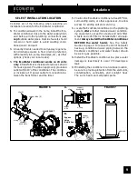
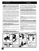
1. INSTALL BYPASS VALVE and/or COPPER
TUBES
IMPORTANT: The support assembly (FIG. 6) is fac-
tory installed. The bypass valve or outlet copper
tube will not insert properly if the support assembly
is reversed or not fully into the valve port.
a.
IF INSTALLING AN ECOWATER BYPASS
VALVE, put lubricated o--ring seals onto both bypass
valve ports (FIG. 6B). Carefully slide the bypass
valve into the softener valve and install the “C”clips.
b.
Slide a lubricated o--ring seal onto each of the
copper tubes. Carefully insert the copper tubes into
the bypass valve (FIG. 6B), or into the softener valve
(FIG. 6 and 6A). Then install the ‘‘C’’clips.
NOTE: For lubrication, use silicone grease ap-
proved for potable water supplies.
IMPORTANT: Be sure the bypass valve and/or
copper tubes are firmly held in place by the plas-
tic ‘‘C’’clips, and the clips are securely in place.
2. TURN OFF WATER SUPPLY
a.
Close the main water supply valve, near the well
pump or water meter.
b.
Shut off the electric or fuel supply to the water
heater.
c.
Open high and low faucets to drain all water from
the house pipes.
3. INSTALLING THREE VALVE BYPASS
If installing a 3--valve bypass system, plumb as
needed using FIG. 3 as a guide. When installing
sweat copper,
be sure to use lead--free solder and
flux
, required by federal and state codes. Use pipe
joint compound on outside pipe threads.
4. MOVE THE ECOWATER UNIT INTO PLACE
Move the EcoWater System Unit (resin tank only if
2--tank model) into installation position. Set it on a
solid, smooth and level surface. If needed, place the
unit on a section of plywood, a minimum of 3/4”thick.
Then, shim under the plywood to level the unit, FIG.
7.
CAUTION:
DO NOT PLACE SHIMS DIRECTLY UN-
DER THE BRINE TANK.
The weight of the tank,
when full of water and salt, may cause the tank to
fracture at the shim.
5. ASSEMBLE INLET AND OUTLET PLUMBING
Measure, cut, and loosely assemble pipe and fittings
from the main water pipe (or from the bypass valves
installed in step 3), to the inlet and outlet copper
tubes, installed in step 1b.
Be sure
hard water
supply pipe
goes to
the valve
inlet side
. Trace the water flow direction to be sure.
CAUTION
: Be sure to fit, align and support all plumb-
ing to prevent putting stress on the softener valve in-
let and outlet. Undo stress may cause damage to
the valve.
continued
ground wire
clamp (2)
nozzle &
venturi
o--ring
elbow
FIGURE 8
FIGURE 9
FIGURE 10
Note: To ease brine tubing con-
nection, use the elbow and o--
ring seal as shown. Lubricate
the o--ring and insert into the el-
bow. Turn the elbow on and tight-
en. Then, back--off up to 1 turn,
as needed.
B
A
3 -- Valve Bypass
OUTLET
VALVE
INLET
VALVE
BYPASS
VALVE
to conditioner
from conditioner
EcoWater Bypass Valves
SERVICE
BYPASS
D
for
SERVICE:
-- Open
the
inlet
and
outlet
valves.
-- Close
the
bypass valve.
D
for
BYPASS:
-- Close
the
inlet
and
outlet
valves.
-- Open
the
bypass valve.
PUSH
IN
for
bypass
PULL
OUT
for
service
brine tubing
nut--ferrule
screen
Install hose clamps before
soldering copper tubes
copper
tubes
hose clamp,
ground (2)
ground wire


