


9. Retaining
Clip
8. Brass
Washer
11. Insulator
Housing
7. Male Contact
7.Basket
Weave
8. Bushing
5. Cable Gland
10. Sealing
Washer
1. Cable Adaptor
9. Mechanical Clamp
8. Bushing
2. Male Skirt
3. Environmental
Cover
4. Coupling
Nut
8. Brass
Washer
9. Retaining
Clip
10. Insulator
Housing
7. Female Contact
1. Cable Adaptor
9. Mechanical
Clamp
8. Bushing
2. Female Skirt
3. Environmental
Cover
7.Basket
Weave 8. Bushing
5. Cable Gland
10. Sealing
Washer
9. Retaining
Clip
8. Brass
Washer
SHEET 2 OF 2
C
DO NOT SCALE DRAWING
REV.
SIZE
CODE IDENT. NO.
TITLE
NEXT ASSY.
APPLICATION
USED ON
CHECKED BY
APPROVED BY
FINISH:
MATERIAL:
TOLERANCES
UNLESS OTHERWISE SPECIFIED
ORIGINAL DATE
REDRAWN DATE
.X
.XX
.XXX
ANGLES
±
± .01
± .005
± 1.5 °
01/24/2013
T. DALY
ADL
IB
THIS IS PROPERTY OF EATON AND CONTAINS CONFIDENTIAL
AND TRADE SECRET INFORMATION. POSSESSION DOES NOT
CONVEY ANY RIGHTS TO LOAN, SELL OR DISCLOSE SAID
INFORMATION. REPRODUCTION OR USE FOR ANY PURPOSE
OTHER THAN WHICH IT WAS SUPPLIED MAY NOT BE MADE
WITHOUT EXPRESS WRITTEN PERMISSION OF EATON.
THIS DRAWING IS ON LOAN AND IS TO BE
RETURNED UPON REQUEST.
PSB
±
±
1.5 °
±
.13
.3
±
in.
mm
CC
HS
Y-T
emplat
e-
C
SW_REV 05/2014
DIR NUMBER:
1020404145/SWD/000/03
HEAT TREATMENT:
DRAWN BY
APPROVED BY
PATT. I.B.
GASKET, SQUARE FLANGE
FIRST MADE FOR CEX
SCALE 2:1
WT. 0.010 LB
0404145
3
A
B
C
D
1
2
3
4
D
C
B
A
4
3
2
1
UNLESS OTHERWISE SPECIFIED, ALL
PRIMARY DIMENSIONS ARE IN
INCHES. DIMENSIONS IN [ ] ARE IN
MILLIMETERS.
THIRD ANGLE PROJECTION
NOTES:
1.
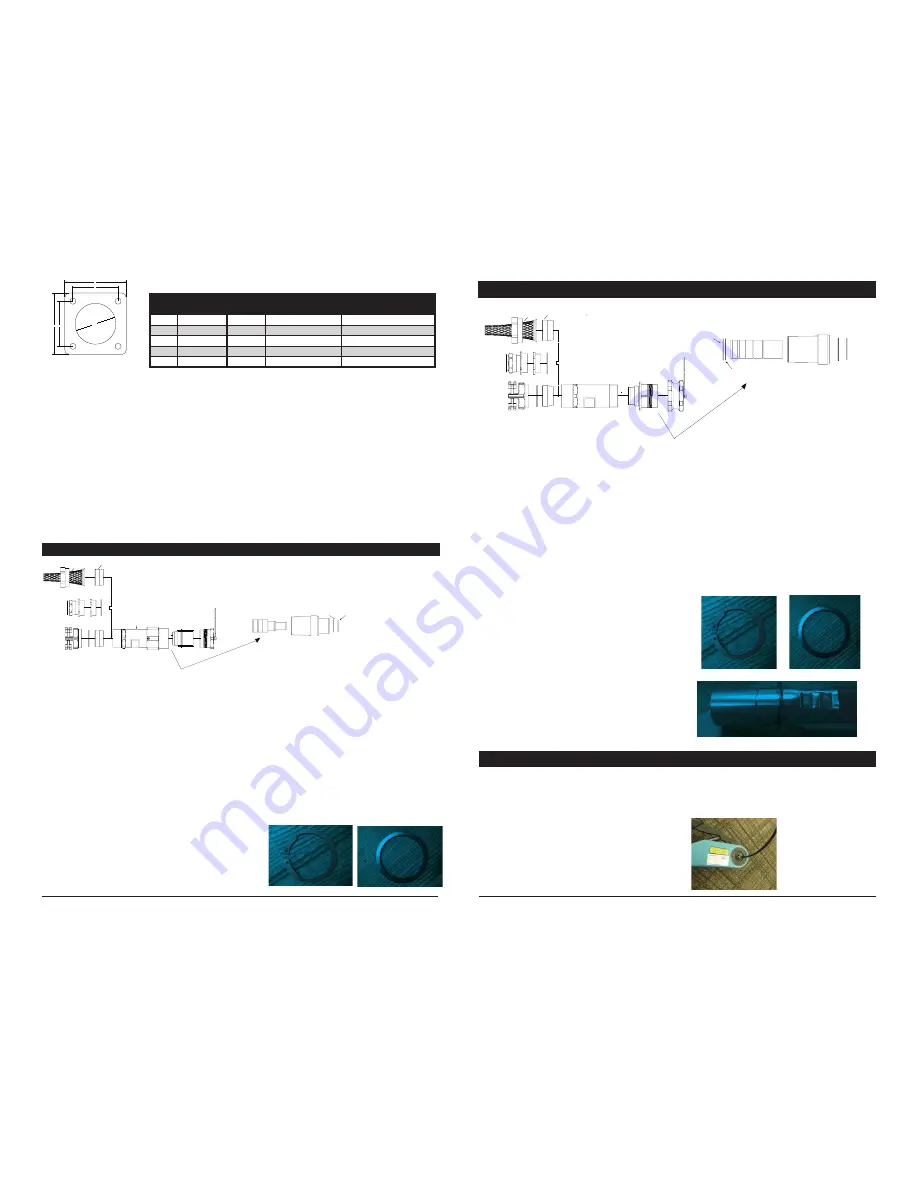
SHELL SIZE
A
in (MM)
B
in (MM)
C (THREAD OF
PANEL MOUNT)
FOR EX d
C - in (MM)
(CLR HOLE SIZE)
FOR EX e
12
2.25 (57.2)
1.65 (42)
M40-1.5-6G
1.614 (41)
16
2.626 (66.7)
2.05 (52)
M50-1.5-6G
2.008 (51)
20
3.0 (76.2)
2.44 (62)
M63-1.5-6G
2.520 (64)
24
3.5 (88.9)
2.83 (72)
M75-1.5-6G
2.992 (76)
B
B
A
A
ØC
Copyright © 2018 Eaton’s Crouse-Hinds Division
IF 1683 • 08/18
Page 3
Copyright © 2018 Eaton’s Crouse-Hinds Division Page 4
IF 1683 • 08/18
Section 6: Cable Prep and Crimp Directions (Excluding Single Pole)
1.
Prepare cables, cutting to length as needed.
2.
Strip outer jacket to length per Table 8.
3.
Strip individual conductors to length per Table 7.
4.
If desired, label wires according to the location # on the
insert.
5.
Install correct positioner per Table 10 onto crimping tool
based on pin size.
6.
Adjust crimping tool knob to required setting based
on pin gauge for 16 gauge-10 gauge contacts.
7.
Place stripped end of conductor into contact socket;
verify that between 1 and 3 mm of bare copper is
exposed between end of contact and insulation.
8. Place contact with wire into crimping tool and fully
squeeze tool until the contact is crimped and released.
9. Repeat Steps 5-8 for each wire and contact as
required.
*Follow crimp tool instructions from tool manual.
Section 4: Installation Instructions for Single Pole Male In-line Plug
A. To disassemble male plug:
1.
Place cable adapter (1) in rubber or aluminum jawed
vice. Unscrew male skirt (2) (left hand thread) from cable
adapter (1), keeping environmental cover (3) on male
skirt (2).
2.
Remove cable adapter (1) from vice and place male skirt
(2) in vice, clamping onto environmental cover (3) with
warning label facing down.
3.
Unscrew coupling nut (4) from environmental cover (3).
4.
Remove male contact (7), brass washer (8) and retaining
clip (9) set to the side.
B. To connect cable to male plug:
1.
Thread cable through cable gland (5). Then thread through
the cable adapter (1) and coupling nut (4) and allow to
rest down the cable out of the way.
2.
Prepare cable and crimp male contact (7) following
directions from Section 8.
3.
Slide the insulator housing (11) over the crimped contact.
4.
Install brass washer (8) followed by retaining clip (9) in
order to secure male contact (7) to insulator housing (11).
5.
Align insulator housing (11) keyway with key on the male
skirt (2) then insert insulator housing (11) fully into male
skirt (2).
C. To reassemble male plug:
1.
Thread coupling nut (4) onto environmental cover (3).
2.
Thread cable adapter (1) (left hand thread) onto the
male skirt (2) and tighten to torque value found in Table
9. Verify male skirt (2) is wrenched fully to the shoulder
of the cable adapter (1) to ensure environmental
integrity.
3A. Torque cable gland (5) to cable adapter (1) per
torque value found in Table 9. Verify sealing washer
(10) in place between cable gland and cable adapter.
3B. Finish installing cable gland to cable per cable gland
manufacturer’s instructions.
4A. If using mechanical clamp (9) or basketweave (7),
pot connector per Section 9.
4B. Screw basketweave (7) or mechanical clamp (9)
onto the end of the cable adapter (1). Screw it
down tight enough to squeeze the bushing (8)
firmly against the cable. Fully tighten with wrench.
4C. For mechanical clamp, tighten cord grip screws to
torque found on Table 9.
Retaining Clip
Brass Washer
Section 5: Installation Instructions for Single Pole Female In-line Receptacle
A. To disassemble female receptacle:
1.
Place cable adapter (1) in rubber or aluminum jawed vice.
Unscrew female skirt (2) (left hand thread) from cable
adapter (1), keeping environmental cover (3) on female
skirt (2).
2.
Remove cable adapter (1) from vice and place female
skirt (2) in vice, clamping onto environmental cover (3)
with warning label facing down.
3.
Remove female contact (7), brass washers (2 pcs) (8)
and retaining clips (2 pcs) (9) set to the side.
B. To connect cable to female plug:
1.
Thread cable through cable gland (5). Then thread
through the cable adapter (1) and allow to rest down the
cable out of the way.
2.
Prepare cable and crimp female contact (7) following
directions from Section 8.
3.
Install retaining clip (9) followed by brass washer (8) into
1st indent in female contact (7) closest to the crimped
cable.
4.
Slide the insulator housing (10) over the crimped contact.
5.
Install brass washer (8) followed by retaining clip (9)
into 2nd indentation furthest from the cable in order to
secure female contact (7) to insulator housing (10).
6.
Align insulator housing (10) keyway with key on the
female skirt (2) then insert insulator housing (10) fully
into female skirt (2).
C. To reassemble female plug:
1.
Thread cable adapter (1) onto female skirt (left hand
threads). Wrench fully to shoulder, following torque
value specified in Table 9.
2A. Torque cable gland (5) to cable adapter (1) per torque
value found in Table 9. Verify sealing washer (10) in
place between cable gland and cable adapter.
2B. Finish installing cable gland to cable per cable gland
manufacturer’s instructions.
3A. If using mechanical clamp (9) or basketweave (7), pot
connector per Section 9.
3B. Screw basketweave (7) or mechanical clamp (9) onto
the end of the cable adapter (1). Screw it down tight
enough to squeeze the bushing (8) firmly against the
cable. Fully wrench tighten.
3C. For mechanical clamp, tighten cord grip screws to
torque found on Table 9.
Retaining Clip
Brass Washer
B3 – Installing Washer and Retaining Clip
E. Mounting to Ex “e” enclosure:
For Ex “e” application, use the gasket and omit the o-ring.
1.
Clean all mating surfaces:
a. Back of square flange skirt (2)
b. Panel surfaces
c. Gasket (4)
d. Locknut (7)
e. Sealing washer (6)
2.
Place gasket (4) on back of square flange skirt (2).
3.
Install square flange skirt (2) through panel, aligning
screw holes.
4.
Install sealing washer (6), as required at back of panel
onto connector.
5.
Thread locknut (7) to panel.
6.
Tighten locknut (7) fully by hand so the connector is
pressed against the panel, compressing the gasket (4).
Using wrench, fully wrench tighten locknut (7). Install
four M5 bolts of appropriate length to go through
enclosure and secure with lock washers and nuts.
Torque bolts to value found in Table 9.
7.
Attach cover lanyard eyelet to one of the fasteners.
F. Mounting to Ex “d” enclosure:
For Ex “d” application, use the o-ring and omit the gasket.
1.
Clean all mating surfaces:
a. Back of square flange skirt (2)
b. Panel surfaces
c. O-ring (5)
2.
Once o-ring (5) is installed onto the back of the
receptacle (2) groove, thread the square flange
receptacle into the Ex “d” enclosure.
3.
Thread the connector assembly into the panel to the
point that the o-ring (5) begins to compress.
4.
Continue to thread connector into enclosure until no
longer possible by hand.
5.
Thread connector to align with next set of bolt holes.
6.
Secure the connector to the enclosure using M5
fasteners, and torque to value found in Table 9.
7.
Attach cover lanyard eyelet to one of the fasteners.
Shell
size
A
in. (mm)
B
in. (mm)
C (thread of panel
mount) for Ex d
C - in. (mm)
(CLR hole size) for Ex e
12
2.25 (57.2)
1.65 (42)
M40-1.5-6G
1.614 (41)
16
2.626 (66.7)
2.05 (52)
M50-1.5-6G
2.008 (51)
20
3.0 (76.2)
2.44 (62)
M63-1.5-6G
2.520 (64)
24
3.5 (88.9)
2.83 (72)
M75-1.5-6G
2.992 (76)
28
4.0 (101.6)
3.23 (82)
M90-1.5-6G
3.582 (91)
Table 1. Panel Mount Installation Dimensions


