


Installing the IAC
3-22
EATON
Powerware
®
9390 IAC-B and IAC-T Installation and Operation Manual
S
164201590 Rev C
powerware.com
34.
Secure the large nut on the UPM 2 hinge.
35.
Proceed to paragraph 3.4.2.
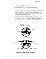
36.
Remove the right-hand screw from the top right-hand door hinge on UPM 1 and
the left-hand screw from the top door hinge on the IAC.
NOTE
Cabinet joining brackets are provided in the field kit for securing each cabinet at
the top and bottom. A small flat bracket joins the top of the cabinets and a larger flat
bracket joins the cabinets at the bottom. The small flat bracket is attached to the cabinet
tops first.
37.
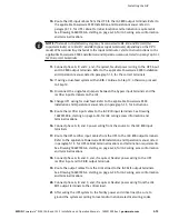
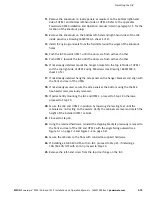
Locate a small flat bracket from the field kit. Align the holes in the small flat
bracket over the door hinge screw holes. Replace the screws in the hinges,
securing the bracket to the cabinets (see Figure 3-13).
38.
Locate a large flat bracket from the field kit. Place one end of the bracket over the
bolt on the bottom side of the lower right-hand hinge on the UPM 1 and the
other end over the bolt on the bottom side of the lower hinge on the IAC (see
Figure 3-13).
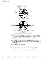
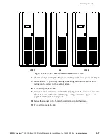
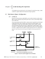
Top View with Small Bracket
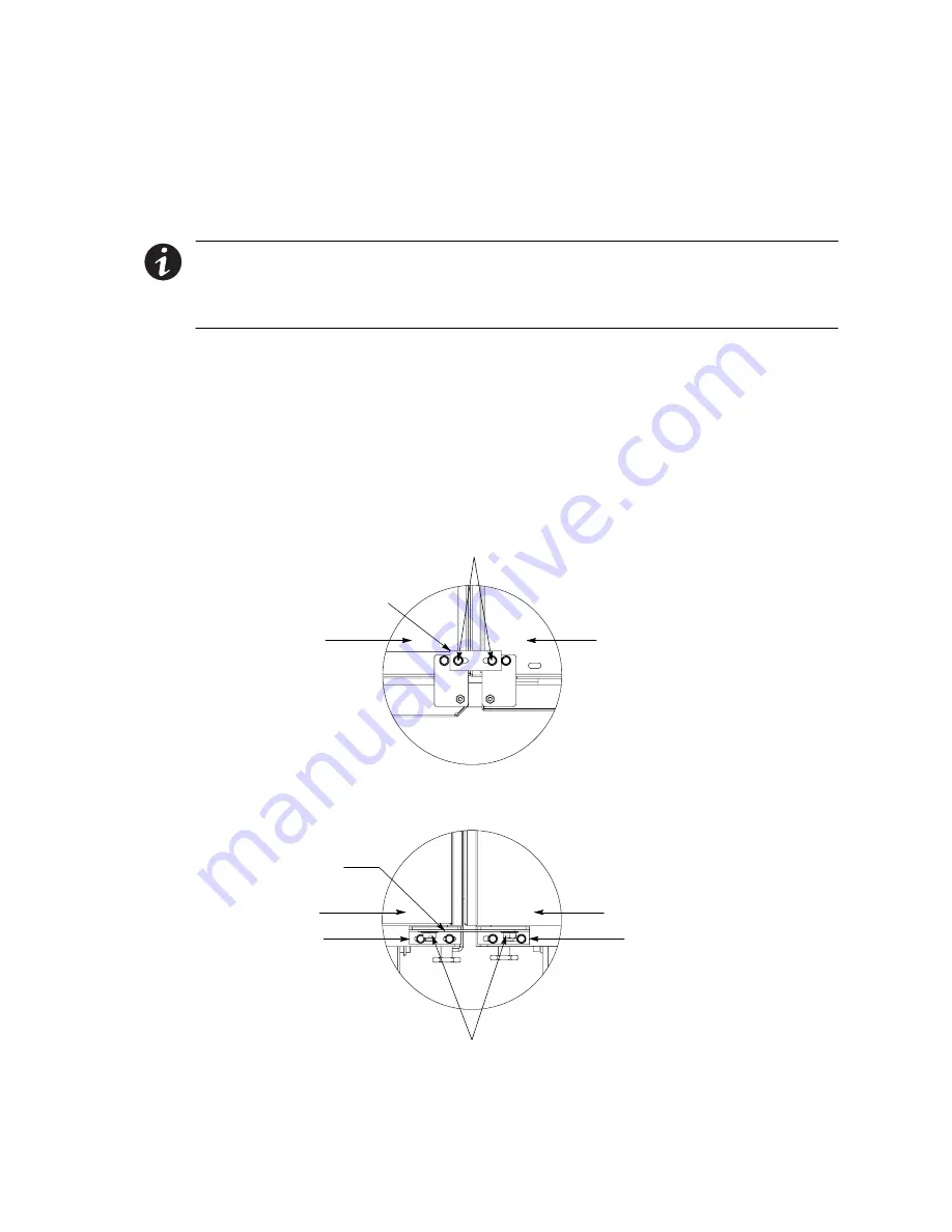
Front View with Large Bracket
Existing Screws
Bracket
from Kit
Nuts from Kit
Existing Hinge
Existing Hinge
Bracket from Kit
UPM 1
IAC
UPM 1
IAC
Figure 3-13. 100–160 kVA UPM 1 to IAC Joining Brackets
Содержание Powerware 9390 IAC-B
Страница 145: ......
Страница 146: ...164201590C 164201590 C...