


2
1 Table of contents
1 Table of contents
2
2 General information
4
2.1
Safety instructions
4
2.2
Qualified personnel
4
2.3 Use
4
2.4
Delivery state
4
3 Introduction
5
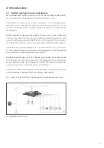
3.1
SCS200 intelligent power distribution
5
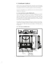
4 Hardware options
6
4.1
Semi-conductor version SCS200-SC…
6
4.1.1
Dimensions SCS200-SC…
6
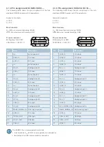
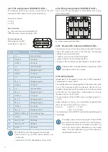
4.1.2
Pin assignment SCS200-SC08-...
7
4.1.3
Pin assignment SCS200-SC12-…
7
4.2
Relay version SCS200-RC…
8
4.2.1
Recommended relays and fuses for SCS200-RC…
8
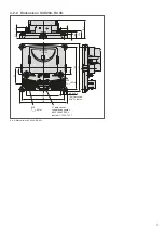
4.2.2
Dimensions SCS200-RC08-…
9
4.2.3
Pin assignment SCS200-RC08-…
10
4.2.4
Relay assignment SCS200-RC08-…
10
4.2.5
Visual LED indication SCS200-RC…
10
4.3
Analog inputs
10
5 Mounting
11
5.1
Cable cross sections
11
6 Software and diagnostic functions
12
6.1
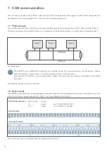
Field bus connection
12
6.2
Integral electronic load protection
12
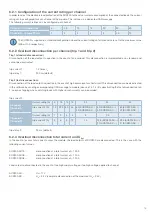
6.2.1
Configuration of the current rating per channel
13
6.2.2
Overload disconnection per channel (trip 1 and trip 2)
13
6.2.3
Overload disconnection total current and U
Bat
13
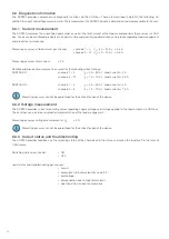
6.3
Diagnostic information
14
6.3.1
Current measurement
14
6.3.2
Voltage measurement
14
6.3.3
Output status and troubleshooting
14
6.3.3.1
Open load
15
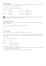
6.4
ON and OFF delay
15
6.5
Sleep mode
15
Содержание SCS200
Страница 1: ...User Manual SCS Smart Control Systems SCS200 intelligent power distribution...
Страница 47: ...47 Notes...


