


10
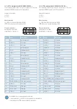
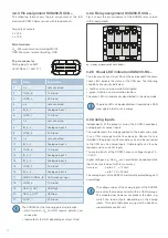
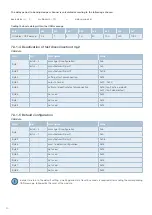
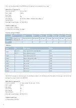
4.2.3 Pin assignment SCS200-RC08-...
The following table shows the pin assignment of the fully
electronic SCS200 Relay version with 8 load outputs.
Ampacity of outputs:
4 x 30 A
4 x 10 A
Main terminals
U
Bat
: M8 screw terminal (marking: MAIN)
GND: M6 screw terminal (marking: GND
21-pole connector
Mating plug: Tyco AMP
LEAVYSEAL 1-1534127-1
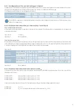
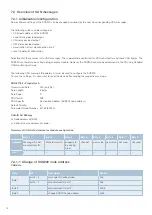
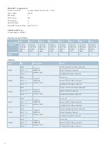
4.2.4 Relay assignment SCS200-RC08-...
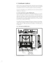
Fig. 4 shows the pin assignment of the SCS200 relay version
with 8 load outputs.
4.2.5 Visual LED indication SCS200-RC…
The relay version has status LEDs on the pcb, beneath the cover.
These LEDs indicate the status of the CAN bus. The following
conditions are visually indicated:
• red: Bus error, communication interrupted
• green: CAN live, communication faultless
The green LED is automatically deactivated in the sleep mode.
The green LED can be deactivated if required via a CAN
message in order to save energy.
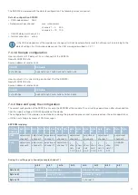
4.3 Analog inputs
Independently of the product version, the SCS200 provides 6
analog inputs or sensor inputs.
The module reads the voltage applied to the inputs and sends
it as a CAN message to other bus devices. Sensor, that are
installed in the proximity of the module, can easily be connected
to the CAN bus via analog inputs. Cable lengths can thus be
reduced and so can ECU inputs.
The analog inputs of the SCS200 cover a voltage range of 0 -
10 VDC.
Higher voltages, e.g. Ubat,
Bat,
can nevertheless be applied to the
inputs, but are read out with less accuracy.
Accuracy:
up to 5 V: ± 125 mV
up to 10 V: ± 200 mV
The analog inputs of the SCS200 are internally protected against
overvoltage.
The voltage values at the analog inputs of the SCS200
are read by the module and sent within a CAN message.
The module does however not process the data, e.g.
switch the load outputs depending on the analog
inputs. This kind of data processing must be done by a
superordinate control unit.
The SCS200 has the following polarity protection:
•
main terminals U
Bat
to GND: reverse polarity non-
conductive
• load outputs to GND: depending on relays fitted
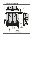
fig. 6: Pin assignment SCS200-SC08-...
fig. 4: Relay assignment SCS200-RC08-...
21
20
2
3
19
1
Pin
Name
Description
1
n.c.
not connected
2
LOAD_8
10 A load
3
LOAD_4
30 A load
4
n.c.
not connected
5
IN_A_1
Analogue input 1
6
LOAD_7
10 A load
7
n.c.
not connected
8
IN_A_3
Analogue input 3
9
LOAD_3
30 A load
10
n.c.
not connected
11
IN_A_4
Analogue input 4
12
LOAD_6
10 A load
13
IN_A_2
Analogue input 2
14
IN_A_5
Analogue input 5
15
LOAD_2
30 A load
16
IN_A_6
Analogue input 6
17
WAKE_SIGNAL_IN CAN wake up input
18
LOAD_5
10 A load
19
CAN_H_OUT
CAN high
20
CAN_L_OUT
CAN low
21
LOAD_1
30 A load
Содержание SCS200
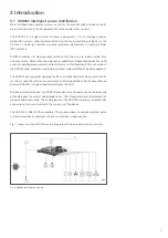
Страница 1: ...User Manual SCS Smart Control Systems SCS200 intelligent power distribution...
Страница 47: ...47 Notes...