70
Network Guide
About the Subnetwork Data Bus
ECL and ECB Distech Controls' controllers use the subnetwork data bus to support various
optional modules that add extra inputs, outputs, sensor inputs (temperature, humidity, CO2,
motion, receive wireless commands from a remote control), and interactive screen menus for
user control. The subnetwork data bus uses the EIA-485 (Electronic Industries Alliance) stan-
dard for data transmission.
Subnetwork Connection Method
Connection to the subnetwork data bus can be made as follows:
•
All ECB and ECL series controllers are equipped with an RJ-45 Subnet Port to quickly
connect expansion modules and sensors in a daisy-chained fashion to the subnetwork
using a Cat 5e cable (standard straight Ethernet patch cable). Any device that connects to
a controller's Subnet Port is collectively referred to as room devices.
•
In addition, the ECB-600 and ECL-600 Series controllers can be connected to one or two
ECx-4XX I/O Extension Modules using the same subnetwork data bus, however the con-
nection is made through the controller's and Subnet screw-type terminal block
connectors using a 2-wire twisted-pair shielded cable.
This is summarized in the table below.
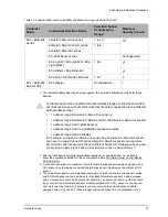
Table 15: Subnetwork Connection Method
Subnetwork Room Device or
Extension Module
Type
Connection Method
Allure EC-Smart-Vue series
Room Device: Sensors
Cat 5e cable with RJ-45 connec-
tors - See
on page 79.
Allure EC-Smart-Comfort series
Allure EC-Smart-Air sensor
series
EC-Multi-Sensor series
ECx-Light-4 / ECx-Light-4D /
ECx-Light-4DALI
Room Device: Application
specific expansion modules
ECx-Blind-4 / ECx-Blind-4LV
ECx-Display
Colour LCD display
ECx-4XX Series I/O Extension
Module
Extension Module
2-wire twisted-pair shielded cable
- See
Содержание ECB-VAV
Страница 1: ...User Guide Network Guide...
Страница 6: ...Table of Contents 4 Network Guide...
Страница 52: ...50 Network Guide...
Страница 70: ...68 Network Guide...
Страница 110: ...108 Network Guide...
Страница 121: ...LonWorks Troubleshooting Network Guide 119...
Страница 122: ...120 Network Guide...
Страница 124: ...122 Network Guide...
Страница 128: ...126 Network Guide...
Страница 134: ...132 Network Guide Figure 75 Example of How to Set a DIP Switch to 82 ON B A For example 82 A 1010 B 010...
Страница 136: ...134 Network Guide...
Страница 137: ...Network Guide...
Страница 138: ...Network Guide_UG_24_EN...


