Subnetwork Installation Guidelines
Network Guide
79
Cat 5e Cable Subnetwork Data Bus
The Cat 5e Cable subnetwork data bus is used to connect compatible room devices (
)
to any Distech Controls ECB/ECL series controller. See
Subnetwork Module Compatibility and
on page 71 for a list of compatible extension / expansion modules.
Cat 5e Cable Subnetwork Data Bus Cable Requirements
The Cat 5e Cable subnetwork data bus uses commonly available Cat 5e structural cabling fit-
ted with RJ 45 connectors. If you make your own patch cable, use Category 5e cable and
crimp the RJ 45 connectors at both ends of the cable either as T568A or T568B.
Never connect an IP (Ethernet) network to the SUBNET PORT connector of a con-
troller or RJ 45 connector of a room device. Equipment damage may result.
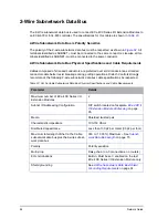
Table 17: Cat 5e Cable Subnetwork Data Bus Physical Specifications and Cable Requirements
Parameter
Details
Maximum number of room devices
Subnetwork Module Compatibility and Supported Quan-
on page 71. See also the controller’s datasheet.
Subnet ID Addressing Configuration
Setting the Subnet ID Addressing for Room Devices
on
page 84.
Media
Cat 5e Patch Cable with RJ-45 Connectors (standard
straight patch cable)
RJ-45 Pin Configuration
Four (4) pairs required. Straight-through wiring. Crimp con-
nectors as per T568A or T568B (both cable ends must be
crimped the same way).
Characteristic impedance
100-130 Ohms
Distributed capacitance
Less than 100 pF per meter (30 pF per foot)
Maximum total length of the Cat 5e
Cable subnetwork data bus plus the
2-Wire subnetwork data bus
300 m (1 000 ft.) Maximum – See
on page 75.
Maximum length of the Cat 5e
Cable subnetwork data bus
180 m (600 ft.) Maximum – See
on page 75.
Polarity
Polarity sensitive
Содержание ECB-VAV
Страница 1: ...User Guide Network Guide...
Страница 6: ...Table of Contents 4 Network Guide...
Страница 52: ...50 Network Guide...
Страница 70: ...68 Network Guide...
Страница 110: ...108 Network Guide...
Страница 121: ...LonWorks Troubleshooting Network Guide 119...
Страница 122: ...120 Network Guide...
Страница 124: ...122 Network Guide...
Страница 128: ...126 Network Guide...
Страница 134: ...132 Network Guide Figure 75 Example of How to Set a DIP Switch to 82 ON B A For example 82 A 1010 B 010...
Страница 136: ...134 Network Guide...
Страница 137: ...Network Guide...
Страница 138: ...Network Guide_UG_24_EN...


