CC7574DKV OPERATOR’S MANUAL
Operating
For additional information and detailed
diagrams on individual saw components, refer
to the CC7574DKV Parts List in conjunction
with this manual.
Tie-Downs
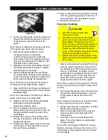
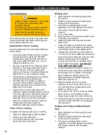
Use the tie-downs when securing the saw in a
truck/trailer for transportation:
•
D-ring on back of saw
•
(2) skid plates or (1) eyebolt on front of
saw
DO NOT over-tighten a chain/rope to the front
end tie-downs, which may bend the frame and
damage the saw.
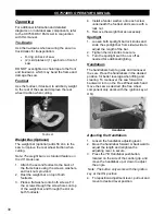
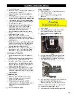
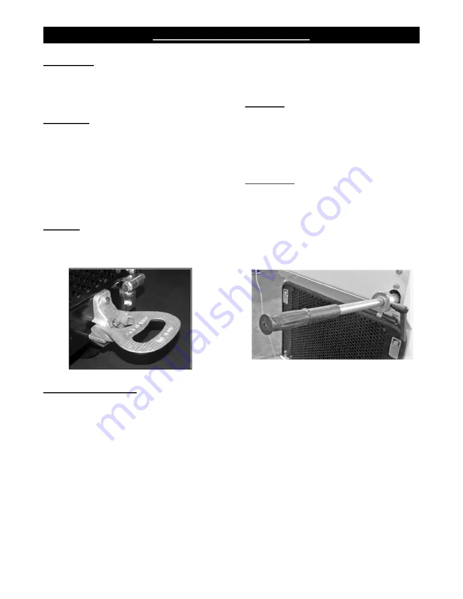
Footrest
Use the footrest, if desired, to add body weight
to the rear of the saw and improve the rear
wheel traction when cutting.
Footrest
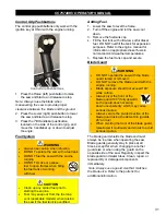
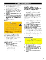
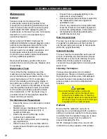
Weight Bar (Optional)
The weight bar (optional) adds 56 Lbs. to the
saw to improve the rear wheel traction when
cutting.
Note: The weight bar is a standard feature on
the 48” blade saw.
1. Attach the second footrest to the back of
the frame base using the screws, washers,
and lock nuts provided.
2. Rest the weight bar on top of both
footrests.
3. Place a flat washer onto both screws. Fit
the screws through the screw holes on top
of the weight bar and through the slot on
both footrests.
4. Install a fender washer onto each screw
underneath the footrest and secure with a
lock nut.
5. Remove the weight bar as necessary.
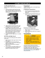
Spotlight
1. Loosen both spotlight bar lock knobs and
slide the spotlight bar from side-to-side to
adjust the length of the bar.
2. Tighten the lock knobs to secure.
3. Turn the spotlight switch on or off as
needed for additional lighting.
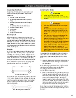
Handlebars
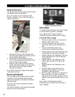
The handlebars help to guide and maneuver
the saw. Place the handlebars in the desired
position for better leverage when lifting and
steering. To maneuver the saw forward or
backward, turn on the
Free Wheel
switch and
move the saw as desired (the free wheel
component only works with the ignition key at
ON
).
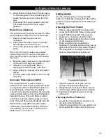
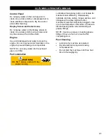
Handlebar
Adjusting the Handlebars
1. Loosen the handlebar adjusting lever.
2. Move the handlebar forward or backward to
adjust the length and retighten the
adjusting lever to secure.
3. Press the
Tilt Handlebar
pushbutton,
located on the side of the control grip, and
move the handlebar up or down to adjust
the angle.
Note: The button only works with the ignition
key at the ON position.
4. To reposition adjustment lever, pull out and
move to desired lever position.
30
Содержание CC7574DKV
Страница 1: ...CORE CUT OPERATOR S MANUAL CC7574DKV CC7574DKV 3 MAY 2022 Part 1802742 01...
Страница 2: ......
Страница 11: ...CC7574DKV OPERATOR S MANUAL CC7574DKV Specifications 11...
Страница 12: ...CC7574DKV OPERATOR S MANUAL CC7574DKV 3 Specifications 12...
Страница 65: ...CC7574DKV OPERATOR S MANUAL Appendix B CC7574DKV RPM Chart CC7574DKV 3 RPM Charts 65...
Страница 66: ...CC7574DKV OPERATOR S MANUAL 66...
Страница 67: ...CC7574DKV OPERATOR S MANUAL CC7574DKV Blade Size Conversion Chart 67...
Страница 68: ...CC7574DKV OPERATOR S MANUAL CC7574DKV 3 Blade Size Conversion Chart 68...
Страница 71: ......

