GB
21
6- User Guide
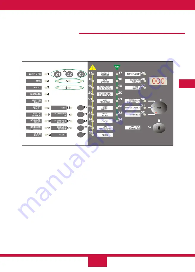
To operate the extinguishing panel properly, please find below details on the functions of
all the indication and control elements of the unit. The operating modes and what to do in
case of an alarm or fault are also explained.
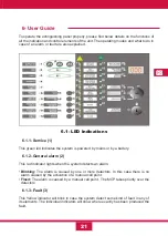
6.1- LED Indications
6.1.1- Service (1)
This green led indicates the system is powered by mains or by a battery.
6.1.2- General alarm (2)
This red indicator lights when the system detects an alarm:
•
Blinking:
The alarm is caused by one or more detectors. In this case there is no
alarm caused by the activation of a manual call point.
•
Fixed:
The alarm is caused by a manual call point . The MCP takes priority over the
detectors.
6.1.3- Fault (3)
This Yellow indicator will blink in case the system detect some kind of fault in any of
its elements. The individual indicators will show where exactly has been produced the
fault.
Содержание CCD-103
Страница 1: ...GB ES ES GUIDE MANUAL FR 3 Zones Conventional fire extinguishant control panel IT ...
Страница 2: ......
Страница 3: ...ES ES Central Convencional de 3 Zonas de detección y 1 Extinción MANUAL DEL USUARIO ...
Страница 4: ......
Страница 6: ......
Страница 14: ...12 ES 4 Guía de conexionado de la PCB ...
Страница 44: ......
Страница 45: ...GB GUIDE MANUAL 3 Zones Conventional fire extinguishant control panel ...
Страница 46: ......
Страница 48: ......
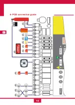
Страница 56: ...12 GB 4 PCB connection guide ...
Страница 86: ......
Страница 87: ...FR FR Centrale conventionnelle à 3 zones de détection et 1 zone d extinction MODE D EMPLOI ...
Страница 88: ......
Страница 90: ......
Страница 98: ...FR 12 4 Guide de branchement de la PCB carte de circuit imprimé ...
Страница 128: ......
Страница 129: ...IT Central Convencional de 3 Zonas de detección y 1 Extinción MANUAL UTENTE ...
Страница 130: ......
Страница 132: ......
Страница 140: ...12 IT 4 Guía de conexionado de la PCB ...
Страница 170: ...55310300 2014 10 14 ...

