22
GB
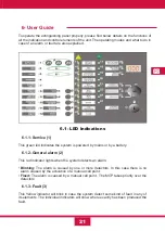
6.1.4 Disablement (4)
This yellow led indicates that there is a zone or a sounder disconnected. If
it is a sounder , the Sounders/Fault/Disabled led will light together with the
disablement led. Otherwise if it is a zone, the yellow led belonging to the
corresponding zone will also light.
6.1.5 Zone alarm Led (5)
This red indicator is associated with a zone, which lights up when the unit detects an
alarm in this zone:
•
Blinking:
The alarm is caused by one or more detectors. In this case there is no
alarm caused by the activation of a manual call point.
•
Fixed:
The alarm is caused by a manual call point. The MCP takes priority over the
detectors.
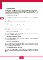
6.1.6- Fault/Disablement/Test Zones LED
Yellow indicator associated with a zone:
•
Blinking:
The associated zone has a fault or is undergoing testing.
•
Fixed:
The associated area is disconnected.
6.1.7- System fault LED (7)
This yellow LED is permanently active when there is any critical situation in the system.
In this case the system is not operational .
6.1.8- Power supply fault LED (8)
This yellow indicator flashes if there is any problem in the power supply, caused by the
mains supply, batteries or fuses.
6.1.9- Out of service LED (9)
This yellow indicator is activated when the panel is not receiving the correct voltage to
operate. There is no mains supply and the voltage supplied by batteries is not enough
for the proper functioning of equipment.
6.1.10- Sounders delayed LED (10)
This yellow LED indicates that the sounder output is time delayed. When there is an
alarm the sounder output will not be activated until pass the delay time configured by
jumper.
Содержание CCD-103
Страница 1: ...GB ES ES GUIDE MANUAL FR 3 Zones Conventional fire extinguishant control panel IT ...
Страница 2: ......
Страница 3: ...ES ES Central Convencional de 3 Zonas de detección y 1 Extinción MANUAL DEL USUARIO ...
Страница 4: ......
Страница 6: ......
Страница 14: ...12 ES 4 Guía de conexionado de la PCB ...
Страница 44: ......
Страница 45: ...GB GUIDE MANUAL 3 Zones Conventional fire extinguishant control panel ...
Страница 46: ......
Страница 48: ......
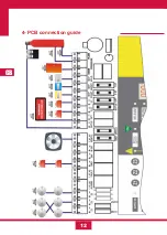
Страница 56: ...12 GB 4 PCB connection guide ...
Страница 86: ......
Страница 87: ...FR FR Centrale conventionnelle à 3 zones de détection et 1 zone d extinction MODE D EMPLOI ...
Страница 88: ......
Страница 90: ......
Страница 98: ...FR 12 4 Guide de branchement de la PCB carte de circuit imprimé ...
Страница 128: ......
Страница 129: ...IT Central Convencional de 3 Zonas de detección y 1 Extinción MANUAL UTENTE ...
Страница 130: ......
Страница 132: ......
Страница 140: ...12 IT 4 Guía de conexionado de la PCB ...
Страница 170: ...55310300 2014 10 14 ...

