


2.
Check the appropriate indicator on the NIC connector. See "
NIC Indicators
" in "Indicators, Messages, and Codes."
l
If the link indicator does not light, check all cable connections.
l
If the activity indicator does not light, the network driver files might be damaged or missing.
Remove and reinstall the drivers if applicable. See the NIC's documentation.
l
Change the autonegotiation setting, if possible.
l
Use another connector on the switch or hub.
If you are using a NIC card instead of an integrated NIC, see the documentation for the NIC card.
3.
Ensure that the appropriate drivers are installed and the protocols are bound. See the NIC's documentation.
4.
Enter the System Setup program and confirm that the NICs are enabled. See "Using the System Setup Program" in your
User's Guide
.
5.
Ensure that the NICs, hubs, and switches on the network are all set to the same data transmission speed. See the network equipment documentation.
6.
Ensure that all network cables are of the proper type and do not exceed the maximum length. See "Network Cable Requirements" in "I/O Connectors."
Responding to a Systems Management Software Alert Message
Systems management software monitors critical system voltages and temperatures, fans, and hard drives in the system. Alert messages appear in the
Alert
Log
window. For information about the
Alert Log
window, see the systems management software documentation.
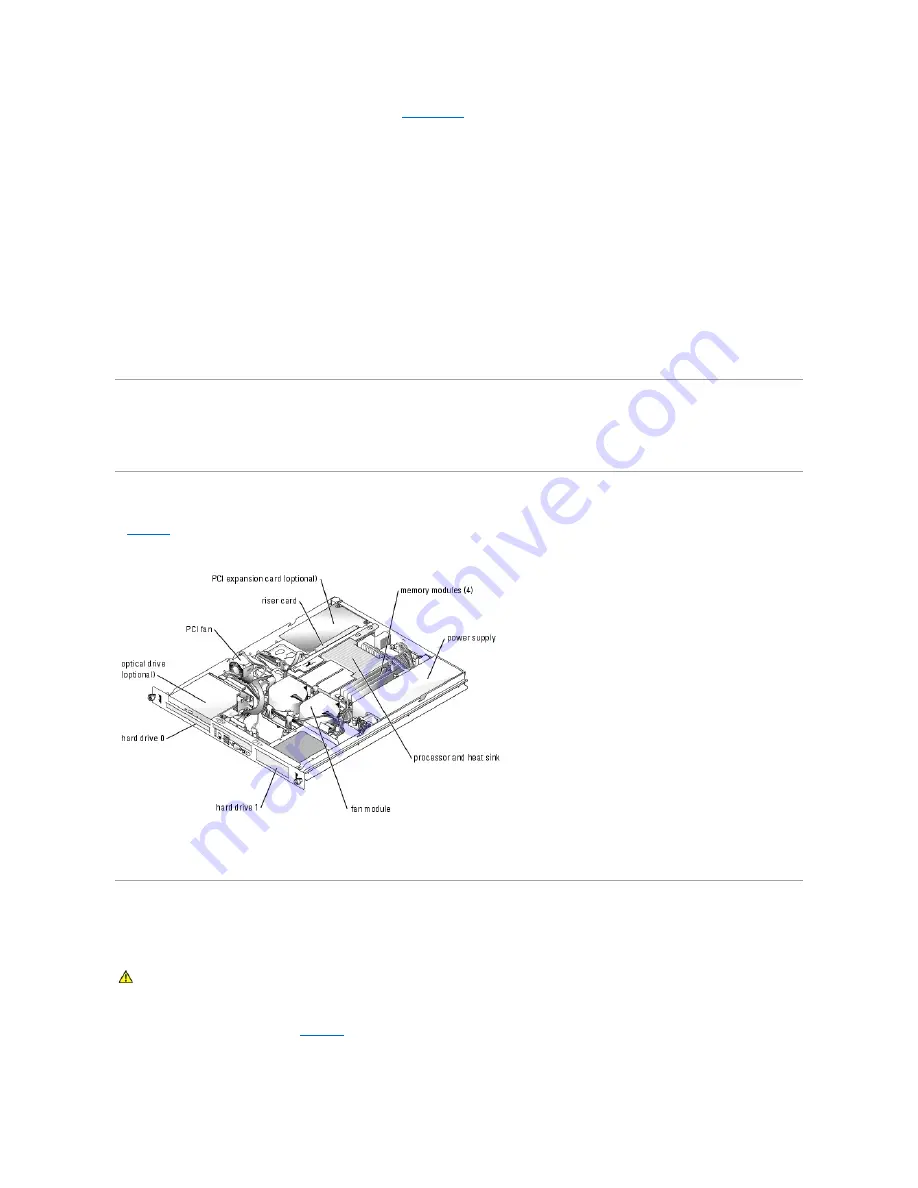
Inside the System
In
Figure 4
-1
, the bezel and system cover are removed to provide an interior view of the system.
Figure 4-1. Inside the System
The system board holds the system's control circuitry and other electronic components. The processor and memory are installed directly on the system board.
Using a riser card, the system can accommodate two expansion cards. The peripheral bays provide space for up to two hard drives and an optional optical
drive. Power is supplied to the system board and drives through one nonredundant power supply.
Opening the System
The system is enclosed by an optional bezel and cover. To upgrade or troubleshoot the system, remove the bezel and cover.
1.
If applicable, remove the bezel. See
Figure 4
-2
.
a.
Unlock the bezel.
b.
Unlatch the left end of the bezel and rotate it away from the front panel.
CAUTION:
Only trained service technicians are authorized to remove the system cover and access any of the components inside the system.
Before performing any procedure, see your
Product Information Guide
for complete information about safety precautions, working inside the
computer and protecting against electrostatic discharge.
Содержание PowerEdge 850
Страница 90: ......
Страница 132: ...Back to Contents Page ...
Страница 137: ...17 Close the system See Closing the System in Troubleshooting Your System Back to Contents Page ...


