background image

Diagnostic Video Tests

A-13

320 x 200 16-Color Graphics Mode 
Screen

The 320- x 200-pixel 16-color graphics mode screen dis-
plays a series of Xs in 16 different colors with the name 
of the color beneath each X. Type 

y

 if all the Xs are the 

correct colors; otherwise, type 

n

640 x 200 16-Color Graphics Mode 
Screen

The 640- x 200-pixel 16-color graphics mode screen dis-
plays a series of hexagons in 16 different colors with the 
name of the color beneath each hexagon. Type 

y

 if all the 

hexagons are the correct colors; otherwise, type 

n

640 x 350 16-Color Graphics Mode 
Screen

The 640- x 350-pixel 16-color graphics mode screen dis-
plays a series of octagons in 16 different colors with the 
name of the color displayed beneath each octagon. Type 

y

 if all the octagons are the correct colors; otherwise, 

type 

n

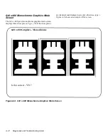
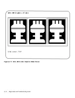
640 x 480 2-Color Graphics Mode 
Screen

The 640- x 480-pixel 2-color graphics mode screen dis-
plays three chess pieces. Type 

y

 if all the chess pieces are 

identical and displayed correctly; otherwise, type 

n

. Fig-

ure A-10 shows an example of this screen. 


Содержание OptiPlex HUB

Страница 1: ... 1267 6 1 7528 6 227 1 8 ...

Страница 2: ......

Страница 3: ... 1267 6 1 7528 6 227 1 8 ...

Страница 4: ...ark of Dell Computer Corporation Pentium is a registered trademark of Intel Corporation Microsoft MS DOS Windows and Windows NT are registered trademarks of Microsoft Corporation CompuServe is a registered trademark of CompuServe Inc and Lotus is a registered trademark of Lotus Development Corporation Other trademarks and trade names may be used in this document to refer to either the entities cla...

Страница 5: ...computer To help prevent electric shock plug the computer and peripheral power cables into properly grounded power sources These cables are equipped with 3 prong plugs to help ensure proper grounding Do not use adapter plugs or remove the grounding prong from a cable If you must use an extension cable use a 3 wire cable with properly grounded plugs To help protect your computer system from sudden ...

Страница 6: ...tatic electricity from your body before you touch any of your computer s electronic components such as the micro processor You can do so by touching an unpainted metal surface on the computer chassis As you continue to work inside the computer periodi cally touch an unpainted metal surface to remove any static charge your body may have accumulated You can also take the following steps to prevent d...

Страница 7: ...ut I O panel of your computer and components inside your computer respectively Chapter 7 Getting Help describes the help tools Dell provides to assist you should you have a prob lem with your computer system It also explains how and when to call Dell for technical assistance Make a copy of the Diagnostics Checklist in Chapter 7 and fill it out as you perform the troubleshooting proce dures If you ...

Страница 8: ...ide last minute updates about technical changes to your system or advanced technical refer ence material intended for experienced users or technicians NOTE Documentation updates are sometimes included with your system to describe changes to your system or software Always read these updates before consulting any other documentation because the updates often con tain information that supersedes the ...

Страница 9: ...are optional Example del drive path filename p Command lines consist of a command and may include one or more of the command s possible parameters Command lines are presented in the Courier New font Example del c myfile doc Screen text is text that appears on the screen of your monitor or display It can be a system message for example or it can be text that you are instructed to type as part of a ...

Страница 10: ...x ...

Страница 11: ...2 Messages and Codes 2 1 System Messages 2 1 System Beep Codes 2 9 Warning Messages 2 13 Diagnostics Messages 2 13 Chapter 3 Finding Software Solutions 3 1 Installing and Configuring Software 3 1 Expanded and Extended Memory 3 1 Using Software 3 2 Error Messages 3 2 Input Errors 3 2 Memory Resident Programs 3 2 Program Conflicts 3 3 Checking for Memory Address Conflicts 3 3 Avoiding Interrupt Assi...

Страница 12: ... 6 Select Under Subtest 4 6 Options Under Subtest 4 6 Test Limits Under Subtest 4 6 About Under Subtest 4 6 Key Help Under Subtest 4 6 Quit Menu Under Subtest 4 6 Options 4 6 Number of Times to Repeat Test s 4 6 Maximum Errors Allowed 4 6 Pause for User Response 4 7 Output Device for Status Messages 4 7 Output Device for Error Messages 4 8 Test Limits 4 8 About 4 8 Key Help 4 8 Quit 4 8 Tests in t...

Страница 13: ...d Disk Drives Test 4 17 IDE CD ROM Drives Test Group 4 17 Subtests 4 17 Why Run an IDE CD ROM Drives Test 4 18 Serial Infrared Ports Test Group 4 18 Subtests 4 18 Why Run a Serial Infrared Ports Test 4 18 Parallel Ports Test Group 4 19 Subtests 4 19 Why Run a Parallel Ports Test 4 19 SCSI Devices Test Group 4 20 Subtests 4 20 Why Run a SCSI Devices Test 4 20 Network Interface Test Group 4 21 Subte...

Страница 14: ...oubleshooting System Memory 6 5 Troubleshooting the Video Subsystem 6 6 Troubleshooting the System Board 6 8 Troubleshooting the Diskette Tape Drive Subsystem 6 9 Checking the Diskette Tape Drive Subsystem 6 9 Troubleshooting a Diskette Drive Subsystem 6 9 Troubleshooting a Non SCSI Internal Tape Drive 6 11 Troubleshooting a SCSI Tape Drive 6 12 Troubleshooting Hard Disk Drives 6 14 Troubleshootin...

Страница 15: ...5 A 2 Character Set Subtest 80 x 25 A 3 Video Scan Alignment Subtest A 4 Character Attributes Subtest 40 x 25 A 6 Character Set Subtest 40 x 25 A 7 Text Mode Color Test A 8 Color Attributes Subtest 80 x 25 A 8 Color Attributes Subtest 40 x 25 A 9 Color Bars Subtest A 9 Text Mode Pages Test A 9 Graphics Mode Test A 10 320 x 200 Graphics Mode Screens A 10 640 x 200 Black White Graphics Mode Screen A...

Страница 16: ...3 Figure A 3 Video Scan Alignment Subtest Screen 1 A 4 Figure A 4 Video Scan Alignment Subtest Screen 2 A 5 Figure A 5 40 Column x 25 Line Character Attributes Subtest Screen A 6 Figure A 6 40 Column x 25 Line Character Set Subtest Screen A 7 Figure A 7 Text Mode Pages Test Screen A 9 Figure A 8 640 x 200 Black White Graphics Mode Screen A 11 Figure A 9 640 x 480 Monochrome Graphics Mode Screen A ...

Страница 17: ...Subtest Screen A 3 Figure A 3 Video Scan Alignment Subtest Screen 1 A 4 Figure A 4 Video Scan Alignment Subtest Screen 2 A 5 Figure A 5 40 Column x 25 Line Character Attributes Subtest Screen A 6 Figure A 6 40 Column x 25 Line Character Set Subtest Screen A 7 Figure A 7 Text Mode Pages Test Screen A 9 Figure A 8 640 x 200 Black White Graphics Mode Screen A 11 Figure A 9 640 x 480 Monochrome Graphi...

Страница 18: ...xx DELL CONFIDENTIAL Preliminary 2 10 98 ...

Страница 19: ... System Messages 2 1 Table 2 2 System Beep Codes 2 10 Table 3 1 Default IRQ Line Assignments 3 3 Table 4 1 Option Parameters 4 7 Table 4 2 Dell Diagnostics Tests 4 9 Table 7 1 Help Tools 7 2 Table 7 2 International Dialing Codes 7 9 Table 7 3 Dell Contact Numbers 7 10 Table A 1 Color Attributes A 8 ...

Страница 20: ...xxii DELL CONFIDENTIAL Preliminary 2 10 98 ...

Страница 21: ...ystem and application programs with Dell s Program Diskette Maker utility If you are using an operating system other than MS DOS see the documentation that came with your operating sys tem for instructions on how to back up your files Basic Checks The following procedure leads you through the checks necessary to solve some basic computer problems 1 Is your computer wet or damaged Yes Go to Chapter...

Страница 22: ...tions and switches Complete the following procedure to check all the con nections and switches 1 Turn off the system including any attached peripherals such as the monitor keyboard printer external drives scanners or plotters Disconnect all the alternating current AC power cables from their power sources 2 If your computer is connected to a power strip turn the power strip off and then on again Is...

Страница 23: ...g on the icon for drive A On a system running MS DOS you can test the drive by inserting a diskette into the drive typing dir a and pressing Enter If the diskette drive access indicator does not light up see Troubleshooting the Diskette Tape Drive Subsystem in Chapter 6 The hard disk drive access indicator The hard disk drive access indicator should quickly flash on and off when you access data on...

Страница 24: ... checking the settings in the System Setup pro gram you have not resolved the problem determine whether you have an EISA system If you have an EISA system see The EISA Configuration Utility found next in this chapter If you do not have an EISA system see Chapter 4 Running the Dell Diagnostics The EISA Configuration Utility If you have a system that can use EISA expansion cards and if you are exper...

Страница 25: ...roblem or to a conflict between your software and hardware If you receive a system message see Table 2 1 for suggestions on resolv ing any problems indicated by the message The system messages are listed alphabetically If you have a Dell PowerEdge system refer to the chapter titled Messages and Codes in your Installation and Trouble shooting Guide NOTE If the system message you received is not lis...

Страница 26: ... structure of the diskette or hard disk drive See your operating sys tem documentation Decreasing available memory One or more SIMMs or DIMMs may be faulty or improperly seated See Troubleshooting System Memory in Chapter 6 Diskette drive 0 seek failure Diskette drive 1 seek failure A cable may be loose or the system configuration information may not match the hardware configuration See Troublesho...

Страница 27: ...sk Drives in Chapter 6 Incompatible Processor CPU0 is B0 step or below Incompatible Processor CPU1 is B0 step or below An old unsupported version of the microprocessor is installed In a single microprocessor system CPU0 refers to the system board microprocessor in a dual microprocessor system it refers to the secondary microprocessor on the add in card The CPU1 message appears only on a dual micro...

Страница 28: ...tion for instructions Keyboard clock line failure Keyboard controller failure Keyboard data line failure Keyboard failure Keyboard stuck key failure A cable or connector may be loose or the keyboard or keyboard mouse controller may be faulty See Troubleshooting the Keyboard in Chapter 5 Memory address line failure at address read value expecting value One or more SIMMs may be faulty or improperly ...

Страница 29: ...ted See Troubleshooting System Memory in Chapter 6 Memory size in CMOS invalid The amount of memory recorded in the system configuration informa tion does not match the memory installed in the computer Reboot the computer If the error appears again see Chapter 7 Getting Help for instructions on obtaining technical assistance Memory tests terminated by keystroke The memory test did not complete Rer...

Страница 30: ...led on it A nonbootable diskette is in drive A Either replace the diskette with one that has a bootable operating system or remove the diskette from drive A and restart the computer Not a boot diskette There is no operating system on the diskette Boot the computer with a diskette that contains an operating system Plug and Play Configuration Error The system has encountered a prob lem in trying to ...

Страница 31: ...oprocessor card is installed in the 2ND_CPU connector Reseat the card and start the system If errors persist see Chapter 7 Getting Help for instructions on obtaining technical assistance NOTE This message indicates a fatal error When a fatal error occurs the system usually cannot be rebooted until an appropriate hardware change has been made Time of day clock stopped The battery may be dead Enter ...

Страница 32: ... POST has queried the EIDE drive for status information The drive has returned a parameter from the call that indicates it has detected possible error conditions for its operating specifications Once your computer finishes booting immediately back up your data and replace your hard disk drive Restore the data to the replaced drive If a replacement drive is not immediately available and the drive i...

Страница 33: ...BIOS has detected that one or both of the thermal probes in the computer are nonoperational You can continue to use the system but be aware that the temperature probe s are disabled and a processor overheat condition will not warn the Thermal Shutdown service to shut down the system NOTE The Pentium Pro microprocessor has a built in thermocouple that halts microprocessor operation if the microproc...

Страница 34: ...DIMMs not being properly identified or used See Troubleshooting System Memory in Chapter 7 3 1 1 Slave DMA register failure Run the System Set Test Group in the Dell Diagnostics if possible See Chapter 4 Running the Dell Diagnostics 3 1 2 Master DMA register failure Run the System Set Test Group in the Dell Diagnostics if possible See Chapter 4 Running the Dell Diagnostics 3 1 3 Master interrupt m...

Страница 35: ...see Chapter 7 Getting Help for instructions on obtaining technical assistance 4 3 1 Memory failure above address 0FFFFh Run the RAM Test Group in the Dell Diagnostics See Chapter 4 Run ning the Dell Diagnostics 4 3 3 Timer chip counter 2 failure Otherwise see Chapter 7 Getting Help for instructions on obtaining technical assistance 4 3 4 Time of day clock stopped Otherwise see Chapter 7 Getting He...

Страница 36: ...Running the Dell Diagnostics 6 1 3 Keyboard controller failure Run the System Set Test Group in the Dell Diagnostics See Chapter 4 Running the Dell Diagnostics 6 1 4 CMOS Register Test failure Run the System Set Test Group in the Dell Diagnostics See Chapter 4 Running the Dell Diagnostics 6 2 1 BIOS shadowing failure Run the System Set Test Group in the Dell Diagnostics See Chapter 4 Running the D...

Страница 37: ...u to respond by typing a y yes or n no NOTE Warning messages are generated by either your application programs or your operating system See Chapter 3 Finding Software Solutions and the docu mentation that accompanied your operating system and application programs Diagnostics Messages When you run a test group or subtest in the Dell Diagnos tics an error message may result These particular error me...

Страница 38: ...2 14 Diagnostics and Troubleshooting Guide ...

Страница 39: ... the programs they infect Several com mercial virus scanning programs are available for purchase and most bulletin board services BBSs archive freely distributed virus scanning programs that you can download with a modem Before installing a program read its documentation to learn how the program works what hardware it requires and what its defaults are A program usually includes installation instr...

Страница 40: ...r configuration Error Messages Error messages can be produced by an application pro gram the operating system or the computer Chapter 2 Messages and Codes discusses the error messages that are generated by the system If you receive an error mes sage that is not listed in Chapter 2 check your operating system or application program documentation Input Errors If a specific key or set of keys is pres...

Страница 41: ... expansion card s address block refer to the documentation for the card Avoiding Interrupt Assignment Conflicts Problems can arise if two devices attempt to use the same interrupt request IRQ line To avoid this type of con flict check the documentation for the default IRQ line setting for each installed expansion card Then consult Table 3 1 to configure the card for one of the available IRQ lines ...

Страница 42: ...3 4 Diagnostics and Troubleshooting Guide ...
Страница 43: ...n error is detected or to terminate testing when an adjustable error limit is reached A menu category called About that briefly describes each test and its parameters Status messages that inform you whether test groups or subtests were completed successfully Error messages that appear if any problems are detected When to Use the Dell Diagnostics Whenever a major component or device in your com put...

Страница 44: ... all its components and devices such as ports For instructions on entering and using the System Setup program see your system documentation Starting the Dell Diagnostics After you complete the preliminary instructions specified in the previous section follow these steps to start the diagnostics 1 Turn off the computer 2 Place your diagnostics diskette in drive A and boot the system NOTE Before you...

Страница 45: ...lable Test Group area lists the diagnostic test groups in the order they will run if you select All from the Run menu category Press the up or down arrow key to highlight a test group On the right side of the screen the System Configu ration area lists the computer s currently detected hardware and some of the relevant settings The lower right side of the screen displays informa tion about your in...

Страница 46: ...ted although you know one is attached to your computer Instead the printer is listed as a parallel port The computer recog nizes the parallel port as LPT1 which is an address that tells the computer where to send outgoing information and where to look for incoming information Because RAM System Set Video Keyboard Mouse Diskette Drives Hard Disk Drives Non SCSI IDE CD ROM Drives Serial Infrared Por...

Страница 47: ... Run Run displays five categories One Selected All Key Help and Quit Menu If you select One all the subtests within the highlighted test group are run If you choose Selected only the selected test groups or the subtests that you selected within the test groups are run If you select All all of the subtests in all of the test groups are run The test groups or subtests are run in the same order as th...

Страница 48: ...e same way as the Options category in the Main menu For information on this category see Options found later in this chapter Test Limits Under Subtest The Test Limits category in the Subtest menu functions the same way as the Test Limits category in the Main menu For information on this category see Test Limits found later in this chapter About Under Subtest The About category in the Subtest menu ...

Страница 49: ...rmation Interchange ASCII text file that you can open in any text viewer or word processor You can also access the result file with the MS DOS type com mand as follows 1 Select Quit to exit the diagnostics and return to the operating system prompt 2 At the operating system prompt type the appro priate command and press Enter type result The contents of the file appear on the screen Table 4 1 Optio...

Страница 50: ...I Devices Test Group allow you to designate limits Whether you select Test Limits for a highlighted test group from the Main menu or a subtest from the Subtest menu you set the limits for all the subtests in that test group When you select Test Limits a new screen appears and the Key Help area lists keys to use with the new screen Press Page Down to select the next menu or submenu Press Esc to ret...

Страница 51: ...me computers include expanded or extended memory all memory is tested System Set CMOS Confidence Test CMEM Confidence Test DMA Controller Test Real Time Clock Test System Timers Test Interrupt Controller Test Reset Button Test System Speaker Test Coprocessor Calculation Test Coprocessor Error Exception Test PC Card Controller Test Thermal Control Test Multiprocessor Test USB Register Test USB Memo...

Страница 52: ...e associated interface Hard Disk Drives Non SCSI Disk Controller Test Forced Error Correction Code Test Seek Test Read Test Write Test Tests drives that use fixed internal disks Also tests the associated interface IDE CD ROM Drives Drive Controller Test Seek Test Read Test Audio Output Test Eject Removable Media Tests an IDE drive that uses removable CD media Also tests the associated interface Se...

Страница 53: ...es allocated to them Network Interface Registers Test Internal Loopback Test External Loopback Test Shared RAM Test Display Information Tests the read and write access capability to the NIC registers Also tests the ability of the NIC to transmit and receive data Audio Software Reset Test Compatibility ID Test Interrupt Test DMA Test FIFO RAM Test Initial Reset Status Test Internal Register Test Du...

Страница 54: ...est confirms the func tionality of the computer s cache controller chip and the cache memory Why Run a RAM Test Faulty memory can cause a variety of problems that may not at first glance appear to be happening in RAM If your computer is displaying one or more of the following symptoms run the subtests in the RAM Test Group to verify that the memory is not at fault A program is not running as usual...

Страница 55: ...evice on the system board Multiprocessor Test For systems with multiprocessors confirms that the secondary microprocessor is operational USB Register Test Checks the onboard registers of the universal serial bus USB interface This subtest does not test USB peripherals USB Memory Structure Test Monitors the ability of a USB controller to process a simple set of memory resident instructions Why Run ...

Страница 56: ...color features of a color monitor Subtests The eight subtests in the Video Test Group confirm the following video functions Video Memory Test Checks the read write capability of video memory in various video modes Video Hardware Test Checks the cursor registers and the horizontal and vertical retrace bit registers in the video controller Text Mode Character Test Checks the video subsystem s abilit...

Страница 57: ...internal microcode of the keyboard and the external interface of the keyboard controller chip for a repeating key signal External Key Pad Test Checks the contact beneath the key for an electrical impulse to ensure that the key is working properly Why Run a Keyboard Test Keyboard problems are not always caused by the keyboard For example a complete lockup of the com puter system rendering the keybo...

Страница 58: ...r defective lines on the diskette cable Seek Test Checks the drive s ability to search for a specified track on the diskette and to position its read write heads to all tracks Read Test Positions the read write heads at each cylinder of the diskette for reading data and verifies that all tracks on the diskette can be read correctly Write Test Positions the read write heads at each cylinder of the ...

Страница 59: ... it Identification of unusable disk space unless it is an unusually large amount over five percent of the possible total should not be regarded as a cause for testing the hard disk drive These are the most common symptoms that might prompt you to test the hard disk drive The hard disk drive fails during the boot routine Seek errors are reported by the operating system or application programs An er...

Страница 60: ...diagnostic tests again If an external loopback connector is not attached to a serial or infrared port the Serial External Transmission Test will fail for that port and the results of this test should therefore be ignored An external modem con nected to the port does not substitute for an external loopback connector Subtests The four subtests in the Serial Infrared Ports Test Group confirm the foll...

Страница 61: ...ternal functions of the parallel port Parallel External Loopback Test Tests the functionality of the control lines through an external loopback connector if an external loopback connector is available Parallel External Interrupt Test Tests the parallel port s ability to generate interrupts from all possible sources if an external loopback connector or printer is available Parallel Printer Pattern ...

Страница 62: ...rifies that all tracks on the device can be written to correctly Audio Output Test Causes the CD ROM drive to begin playing the first audio track on an audio CD To determine whether the test passed listen to the audio output of the drive NOTE To conduct the Audio Output Test you must select it individually It will not run as part of the test group Eject Removable Media Causes a CD ROM drive to eje...

Страница 63: ...figuration information about the NIC This information includes the net work address used for communication on the local area network LAN Why Run a Network Interface Test Running a subtest in the Network Interface Test Group helps diagnose problems that may be encountered while the system is operating in a network environment Most network failures are caused by one of the following Poor network con...

Страница 64: ... microphone Why Run an Audio Test If you do not hear sounds from your built in speakers when you expect to it is possible that your operating system or sound application uses resource settings different from those of the audio controller in the computer In the absence of an expected sound first check the documentation that accompanied your operating system or sound application to see if the sound ...

Страница 65: ...ly See Chapter 6 Checking Inside Your Computer for troubleshooting procedures for video expansion cards video memory and your computer s video logic If information on the monitor screen is displayed incor rectly or not at all complete the following steps to determine the problem 1 Turn on the system including any attached peripherals 2 Adjust the switches and controls as specified in the monitor s...

Страница 66: ...g the keyboard cable from your computer s back panel and plug in a working keyboard Is the problem resolved Yes You probably need a new keyboard See Chap ter 7 Getting Help for instructions on obtaining technical assistance No Go to step 3 3 Insert the Dell Diagnostics Diskette into drive A reboot the system and run the Keyboard Test Group in the Dell Diagnostics See Chapter 4 Running the Dell Dia...

Страница 67: ... Serial Port 2 and Parallel Port categories to Auto and change the setting for the Mouse category to On then reboot the system Is the problem resolved Yes You have fixed the problem No Go to step 3 3 Check the contents of your start up files such as autoexec bat and config sys See Installing and Configuring Software in Chapter 3 Are the port configuration commands correct Yes Go to step 5 No Go to...

Страница 68: ... Troubleshooting the Basic I O Functions indicates that the problem is with a device connected to one of the serial ports follow these steps 1 Turn off the computer and any peripheral devices connected to the serial ports Are two serial devices connected to the computer Yes Go to step 2 No Go to step 4 2 Disconnect the devices from serial ports 1 and 2 and connect the malfunctioning serial device ...

Страница 69: ...ned in this guide and elsewhere in Dell documentation Always follow the instructions closely Working inside your computer is safe if you observe the following precautions In addition Dell recommends that you periodically review the safety instructions at the front of this guide Removing and Replacing the Computer Cover To troubleshoot problems inside your computer you need to remove the computer c...

Страница 70: ...structions 7 Replace the computer cover and reconnect the system to AC power Also reconnect any tele phone or telecommunication lines to the computer 8 Insert the Dell Diagnostics Diskette into drive A reboot the system and run the System Set Test Group in the Dell Diagnostics See Chapter 4 Running the Dell Diagnostics Do the tests complete successfully Yes Your system is operating properly No See...

Страница 71: ...ources Also disconnect any telephone or telecommunication lines from the computer 2 Remove the computer cover 3 Check the connection of the battery to the system board Some systems have a coin cell battery that snaps into a socket on the system board Other systems have a battery with a cable that attaches to a header connec tor on the system board Is the battery firmly attached to the battery sock...

Страница 72: ... step 7 No Go to step 6 6 Reconnect the cable connectors to the appropri ate connectors on the expansion cards Is the problem resolved Yes The cable connections were loose You have fixed the problem No Go to step 7 7 Inspect all jumpers and configuration switches on each expansion card Most Industry Standard Architecture ISA expansion cards have configuration settings for an interrupt request IRQ ...

Страница 73: ...ive A Repeat steps 15 16 and 17 for each of the remaining expansion cards that you removed in step 11 Have you reinstalled all of the expansion cards with out encountering a test failure Yes You have fixed the problem No See Chapter 7 Getting Help for information on obtaining technical assistance Troubleshooting System Memory A computer memory problem can be a faulty single in line memory module S...

Страница 74: ...lled in an expansion slot Is a memory expansion card installed Yes Go to step 12 No Go to step 14 12 Check the memory expansion card s documenta tion to determine whether the card is configured correctly Is the memory expansion card configured correctly Yes Go to step 13 No Go to step 14 13 Reconfigure the memory expansion card 14 Replace the computer cover reconnect the system to AC power reconne...

Страница 75: ...lephone or telecom munication lines and turn it on 7 Insert the Dell Diagnostics Diskette into drive A and reboot the system Run the Video Test Group again Is the problem resolved Yes The configuration jumpers were set incorrectly You have fixed the problem No Go to step 8 8 Turn off the system disconnect it from AC power and remove the computer cover Also disconnect any telephone or telecommunica...

Страница 76: ...gram and update the system configuration information 6 Insert the Dell Diagnostics Diskette into drive A and reboot the system Run the System Set Test Group in the Dell Diagnostics See Chapter 4 Running the Dell Diagnostics Do the tests complete successfully Yes Go to step 7 No Go to step 12 7 Remove the Dell Diagnostics Diskette from drive A turn off the system disconnect it from AC power and rem...

Страница 77: ...stem to verify that the sys tem configuration information is correct for the installed diskette drive s If after completing these steps the system boots cor rectly and the monitor no longer displays a system error message the problem is resolved If you continue to have problems however proceed with the appropriate diskette tape drive subsystem troubleshooting procedure Checking the Diskette Tape D...

Страница 78: ...cards See your system documentation for instructions 7 Replace the computer cover reconnect the system to AC power insert the Dell Diagnostics Diskette into drive A and reboot the system Does the system boot properly from the Dell Diag nostics Diskette Yes An expansion card may be conflicting with the diskette tape drive logic or you may have a faulty expansion card Go to Checking the Diskette Tap...

Страница 79: ...ernal tape drive in which case a special tape drive controller card must be installed in one of the expansion slots The troubleshoot ing procedure in this subsection applies specifically to internal tape drives Tape drive problems usually result from a defective tape drive a defective tape cartridge or software Follow these steps to troubleshoot a non SCSI internal tape drive 1 Remove the tape tha...

Страница 80: ...ower reconnect any telephone or telecom munication lines and turn on the computer Is the problem resolved Yes The IRQ jumper settings were incorrect You have fixed the problem No See Chapter 7 Getting Help for instructions on obtaining technical assistance Troubleshooting a SCSI Tape Drive A SCSI tape drive can be either an internal device installed in one of the externally accessible drive bays o...

Страница 81: ... cable connection to the tape drive Are the cables firmly connected Yes Go to step 9 No Go to step 8 8 Reseat the cable connectors replace the computer cover reconnect the system to AC power and turn it on Is the problem resolved Yes You have fixed the problem No Go to step 9 9 Turn off the system including any attached peripherals and disconnect all the AC power cables from their power sources Th...

Страница 82: ...o use the automatic drive type detect feature to correctly set the drive type number and the drive parameters for each drive Are the system configuration settings correct for the installed hard disk drive Yes Go to step 3 No Go to step 2 2 Correct the system configuration settings and reboot the system Is the problem resolved Yes The system configuration settings were set incorrectly You have fixe...

Страница 83: ...ile structure was proba bly corrupt You have fixed the problem No Go to step 14 14 See Chapter 7 Getting Help for instructions on obtaining technical assistance Troubleshooting SCSI Hard Disk Drives in a System Without a SCSI Backplane Board Use the following procedure to troubleshoot a hard disk drive problem if your system includes one or more SCSI hard disk drives and does not contain a SCSI ba...

Страница 84: ...isabled as appropriate See the documentation for the hard disk drive for instructions on selecting the SCSI ID and enabling or disabling termination Is the hard disk drive configured correctly Yes Go to step 13 No Go to step 12 12 Reconfigure the hard disk drive s SCSI ID and termination settings as appropriate Reinstall the hard disk drive Replace the computer cover reconnect the system to AC pow...

Страница 85: ...o step 5 5 Determine whether the system has a Dell SCSI Array DSA controller card Does the system have a DSA controller card Yes Go to step 6 No Go to step 15 6 Run the DSA Manager program to see if it can determine which hard disk drive is faulty See the Dell SCSI Array User s Guide for instruc tions on running the DSA Manager Can the DSA Manager identify the faulty drive Yes Go to step 26 No Go ...

Страница 86: ...ot firmly seated in the connector on the SCSI backplane board or one of the cables in the drive carrier was installed incor rectly You have fixed the problem No Go to step 14 14 Remove the drive carrier and install it in another drive bay Is the problem resolved Yes The SCSI backplane board has a defective con nector See Chapter 7 Getting Help for instructions on obtaining technical assistance No ...

Страница 87: ...able connections to the SCSI backplane board and to the SCSI host adapter Check the DC power cable connection to the SCSI backplane board See your system documentation for the location of the cable connectors on the SCSI backplane board Are the cables firmly connected Yes Go to step 24 No Go to step 23 22 Reseat the cable connectors reconnect the com puter and peripherals to their AC power sources...

Страница 88: ...6 20 Diagnostics and Troubleshooting Guide ...

Страница 89: ...OTE You may also find these questions and answers in the Dell Q A for certain systems For more information see Dell Q A found later in this chapter 2 Review the remaining documentation that accom panied your Dell system To decide which document has the answers you need consult the Preface of your system documentation 3 Run the diagnostics for your Dell system See Chapter 4 Running the Dell Diagnos...

Страница 90: ...BS Frequently asked questions Frequently Asked Questions cards Dell Q A AutoTech service Information about Dell its products and its service and support policies TechFax service TechConnect BBS World Wide Web on the Internet Installation instructions System documentation technical support service AutoTech service Interrupt maps TechFax service Ordering parts Technical support service TechConnect B...

Страница 91: ...ng addresses World Wide Web http www dell com http www dell com intl apcc for Asian Pacific countries only http www dell com euro for Europe only Anonymous FTP ftp dell com Log in as user anonymous and use your e mail address as your password Electronic Support Service support us dell com apsupport dell com for Asian Pacific countries only Electronic Quote Service sales dell com apmarketing dell c...

Страница 92: ... in this chapter NOTE TechFax is not always available in all locations outside the continental U S Please call your local Dell representative for information on availability TechConnect BBS Use your modem to access Dell s TechConnect Bulletin Board Service BBS 24 hours a day seven days a week The service is menu driven and fully interactive The modem settings for the BBS are 8 bit no parity 1 stop...

Страница 93: ... to help For the telephone number to call see Dell Contact Numbers found later in this chapter Returning Items for Warranty Repair or Credit Prepare all items being returned whether for repair or credit as follows 1 Call Dell to obtain an authorization number and write it clearly and prominently on the outside of the box For the telephone number to call see Dell Contact Numbers found later in this...

Страница 94: ...pecific Dell system to better understand your particular question NOTE Have your express service code ready when you call The code helps Dell s automated support telephone system direct your call more efficiently If possible turn your system on before you call Dell for technical assistance and call from a telephone at or near the system You may be asked to type some commands at the keyboard relay ...

Страница 95: ...________________________________________________________________________________________ Are you connected to a network yes no Network version and network card _______________________________________________________________ Programs and versions __________________________________________________________________________ _______________________________________________________________________________...

Страница 96: ...nd then the local number as shown in the following illustration To place a long distance call within your own country use area codes instead of international access codes country codes and city codes For example to call Paris France from Montpellier France dial the area code plus the local number as shown in the following illustration The codes required depend on where you are calling from as well...

Страница 97: ...mark Horsholm 009 45 Not required Finland Helsinki 990 358 9 France Paris Montpellier 00 33 1 4 Germany Langen 00 49 6103 Hong Kong 001 852 Not required Ireland Bray 16 353 1 Italy Milan 00 39 2 Japan Kawasaki 001 81 44 Korea Seoul 001 82 2 Luxembourg 00 352 Macau 853 Not required Malaysia Penang 00 60 4 Mexico Colonia Granada 95 52 5 Netherlands Amsterdam 00 31 20 New Zealand 00 64 Norway Lysaker...

Страница 98: ...tomer Technical Support Dell Dimension systems only 1 300 65 55 33 Customer Technical Support Other systems toll free 1 800 808 378 Customer Care toll free 1 800 819 339 Corporate Sales toll free 1 800 808 385 Transaction Sales toll free 1 800 808 312 Fax toll free 1 800 818 341 Austria Vienna Switchboard 491 04 0 Technical Support 0660 8779 Belgium Brussels Customer Technical Support 02 4819288 S...

Страница 99: ... Toronto 416 758 2400 Customer Technical Support toll free 1 800 847 4096 Sales Direct Sales from outside Toronto toll free 1 800 387 5752 Sales Direct Sales from within Toronto 416 758 2200 Sales Federal government education and medical toll free 1 800 567 7542 Sales Major Accounts toll free 1 800 387 5755 TechConnect BBS Austin Texas U S A 512 728 8528 TechFax toll free 1 800 950 1329 Chile Sant...

Страница 100: ...chboard Paris 01 47 62 68 50 Switchboard Montpellier 04 67 06 65 51 Germany Langen Customer Technical Support 06103 971 200 Customer Care 06103 971 500 TechConnect BBS 06103 971 666 Sales 06103 971 460 Hong Kong NOTE Customers in Hong Kong call Malaysia for technical assistance for Dell Dimension systems and for customer assistance Technical Support Dell Dimension systems only Penang Malaysia 810 ...

Страница 101: ...Switchboard 044 556 4300 Korea Seoul NOTE Customers in Korea call Malaysia for customer assistance Technical Support toll free 080 200 3800 Transaction Sales toll free 080 200 3600 Corporate Sales toll free 080 200 3900 Customer Service Penang Malaysia 810 4949 Fax 394 3122 Switchboard 287 5600 For technical assistance in this country after normal working hours use one of the following numbers 353...

Страница 102: ...ssels Belgium 02 481 92 44 TechFax Amsterdam Netherlands 682 91 06 TechConnect BBS Amsterdam Netherlands 686 65 04 Macau NOTE Customers in Macau call Malaysia for technical assistance for Dell Dimension systems and for customer assis tance Technical Support Dell Dimension systems only Penang Malaysia 810 4948 Technical Support Other systems toll free 0800 582 Customer Service Penang Malaysia 810 4...

Страница 103: ... 682 7171 Corporate Sales 020 581 8818 Corporate SalesFax 020 686 8003 TechConnect BBS 020 686 6504 New Zealand Technical Support Dell Dimension systems only 2 50 GST per call 0900 51010 Technical Support Other systems 0800 446 255 Customer Service 0800 444 617 Sales 0800 441 567 Fax 0800 441 566 Norway Lysaker Customer Technical Support and Customer Service 22 67 50 00 Sales 67 125 711 Poland War...

Страница 104: ... China Hong Kong Japan Korea Macau Malaysia New Zealand Singapore Taiwan and Thailand see individual listings for these countries Customer Technical Support Customer Service and Sales Penang Malaysia 60 4 810 4810 Spain Madrid Technical Support 91 902 100 130 Customer Service 91 329 10 80 TechConnect BBS 91 329 33 53 Sales 91 902 100 185 Switchboard 91 722 92 00 Sweden Upplands Vasby Technical Sup...

Страница 105: ...sia for customer assistance Technical Support toll free 0880 060 07 Customer Service Penang Malaysia 810 4949 Sales toll free 0880 060 06 U K Bracknell Customer Technical Support Dell Dimension systems 01344 720111 Customer Technical Support Other systems 01344 723723 Customer Care 01344 720110 TechFax 01344 723178 TechConnect BBS 01344 723858 Sales 01344 720000 For technical assistance in this co...

Страница 106: ... Service 512 728 1681 Fee Based Technical Support toll free 1 800 433 9005 Sales Catalogs toll free 1 800 426 5150 Spare Parts Sales Dell Direct1 toll free 1 800 274 1490 Major Accounts2 toll free 1 800 357 3355 Fax toll free 1 800 727 8320 TechFax toll free 1 800 950 1329 TechConnect BBS 512 728 8528 Switchboard 512 338 4400 1 Use this telephone number if your call is about a system purchased for...

Страница 107: ...quire the user to respond with the following steps 1 Examine a displayed image for correctness 2 If an image is correct type y 3 If an image is incorrect type n The following sections describe each of the tests in the Video Test Group Video Memory Test The Video Memory Test verifies the integrity of the video memory either on the system board or on a video expansion card As the test runs it descri...

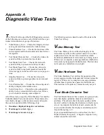
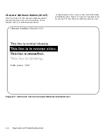
Страница 108: ...x 25 The 80 column x 25 line character attributes subtest dis plays four lines of text that demonstrate normal intensity video reverse video intensified video and blinking video Figure A 1 shows an example of the 80 column x 25 line character attributes subtest screen Figure A 1 80 Column x 25 Line Character Attributes Subtest Screen Is this correct Y N Character Attributes Test 80 x 25 ...

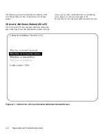
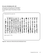
Страница 109: ...plays all 256 characters in the American Standard Code for Infor mation Interchange ASCII character set in 80 column by 25 line text mode Figure A 2 shows an example of the character set subtest screen Figure A 2 80 Column x 25 Line Character Set Subtest Screen Is this correct Y N Character Set Test 80 x 25 ...

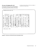
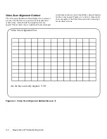
Страница 110: ... lines which should be straight and evenly spaced The second screen is a pattern of boxes arranged in columns and rows which should have straight borders and be evenly spaced Figures A 3 and A 4 respectively show examples of the first and second video scan align ment subtest screens Figure A 3 Video Scan Alignment Subtest Screen 1 Are the lines correctly aligned Y N Video Scan Alignment Test ...

Страница 111: ...Diagnostic Video Tests A 5 Figure A 4 Video Scan Alignment Subtest Screen 2 Are the boxes correctly aligned Y N Video Scan Alignment Test ...

Страница 112: ...f text in 40 column by 25 line double wide text mode that demonstrate normal intensity video reverse video intensified video and blinking video Figure A 5 shows an example of the 40 column x 25 line character attributes subtest screen Figure A 5 40 Column x 25 Line Character Attributes Subtest Screen Is this correct Y N Character Attributes Test 40 x 25 ...

Страница 113: ...ubtest displays all 256 characters in the ASCII character set in 40 column by 25 line double wide text mode Figure A 6 shows an example of the 40 column x 25 line character set subtest screen Figure A 6 40 Column x 25 Line Character Set Subtest Screen Is this correct Y N Character Set Test 40 x 25 ...

Страница 114: ...umber in a unique foreground color and each column has a unique background color Where the same foreground and background color intersect the hexadecimal number is not visible Type y if each character is displayed cor rectly otherwise type n Table A 1 indicates the color in each of the rows and columns Table A 1 Color Attributes Row or Column Number Foreground Color Background Color 0 black black ...

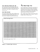
Страница 115: ...color bar is displayed correctly otherwise type n Text Mode Pages Test The Text Mode Pages Test checks the video subsystem s ability to map and present all available video pages on the monitor screen one page at a time The test displays eight successive screens the first of which contains 21 lines of 77 zeros The remaining seven screens are identi cal to the first except that each screen substitut...

Страница 116: ...system does not support the video mode being tested 320 x 200 Graphics Mode Screens The Graphics Mode Test displays two successive 320 x 200 pixel graphics mode screens The first screen displays three pyramids in red green and yellow The second screen displays three pyramids in magenta cyan and white Type y if all the pyramids are the correct colors otherwise type n 640 x 200 Black White Graphics ...

Страница 117: ...Diagnostic Video Tests A 11 Figure A 8 640 x 200 Black White Graphics Mode Screen Is this correct Y N 640 x 200 Graphics Black White ...

Страница 118: ...0 pixel monochrome graphics mode screen displays three chess pieces Type y if all the chess pieces are identical and displayed correctly otherwise type n Figure A 9 shows an example of this screen Figure A 9 640 x 480 Monochrome Graphics Mode Screen Is this correct Y N 640 x 480 Graphics Monochrome ...

Страница 119: ... name of the color beneath each hexagon Type y if all the hexagons are the correct colors otherwise type n 640 x 350 16 Color Graphics Mode Screen The 640 x 350 pixel 16 color graphics mode screen dis plays a series of octagons in 16 different colors with the name of the color displayed beneath each octagon Type y if all the octagons are the correct colors otherwise type n 640 x 480 2 Color Graphi...

Страница 120: ...A 14 Diagnostics and Troubleshooting Guide Figure A 10 640 x 480 2 Color Graphics Mode Screen Is this correct Y N 640 x 480 Graphics 2 Colors ...

Страница 121: ...ors in each asterisk Type y if all the asterisks appear to be correct otherwise type n 1280 x 1024 16 Color Graphics Mode Screen The 1280 x 1024 pixel 16 color graphics mode screen displays a series of squares in 16 different colors located in various positions on the screen Type y if all the squares appear to be correct otherwise type n Color Palettes Test The Color Palettes Test checks the video...

Страница 122: ... When this test is running four screens appear sequentially a red screen a green screen a blue screen and a white screen Check each screen for missing pixels and verify that the correct color is being displayed When the test is complete a message asks if you are sat isfied with the quality of the colors Type y if all the pixels were present and if the correct colors were dis played otherwise type ...

Страница 123: ...bits per second BTU British thermal unit BZT Bundesamt fur Zulassungen in der Telekommunikation C Celsius CCFT cold cathode fluorescent tube CD compact disc CD ROM compact disc read only memory CGA color graphics adapter cm centimeter s CMOS complementary metal oxide semiconductor C O D collect on delivery cpi characters per inch cpl characters per line CPU central processing unit DAC digital to a...

Страница 124: ... file allocation table FCC Federal Communications Commission FIFO first in first out ft feet g gram s G gravities GB gigabyte s Abbreviation or Acronym Description GUI graphical user interface h hexadecimal HMA high memory area HPFS High Performance File System Hz hertz I O input output ID identification IDE integrated drive electronics IR infrared IRQ interrupt request ISA Industry Standard Archi...

Страница 125: ...pheral Component Interconnect Abbreviation or Acronym Description PCMCIA Personal Computer Memory Card International Association PGA pin grid array POST power on self test ppm pages per minute PQFP plastic quad flat pack PS 2 Personal System 2 PVC polyvinyl chloride QIC quarter inch cartridge RAM random access memory RAMDAC random access memory digital to analog converter REN ringer equivalence nu...

Страница 126: ... V volt s VAC volt s alternating current VDC volt s direct current VDE Verband Deutscher Elektrotechniker VESA Video Electronics Standards Association VGA video graphics array VLSI very large scale integration VRAM video random access memory W watt s WH watt hour s XMM extended memory manager XMS eXtended Memory Specification ZIF zero insertion force Abbreviation or Acronym Description ...

Страница 127: ...Color Palettes Test A 1 A 15 computer cover removing and replacing 6 1 connections and switches troubleshooting 1 2 D Dell Diagnostics about 2 1 4 1 diskette 4 1 list of tests 4 9 starting 4 2 video tests A 1 video tests about A 1 Dell Q A 7 3 device drivers 3 3 diagnosing problems 7 1 Diagnostics Checklist 7 7 diagnostics diskette 4 1 Diskette Drives Test Group 4 16 diskette tape drive subsystem ...

Страница 128: ...ics tests 4 17 IDE CD ROM Drives Test Group 4 17 hard disk drives continued SCSI Devices Test Group 4 20 troubleshooting IDE hard disk drives 6 14 troubleshooting SCSI drives 6 15 6 17 Hard Disk Drives Non SCSI Test Group 4 16 help from Dell Computer Corporation 7 1 help tools AutoTech service 7 3 Dell Diagnostics program 7 3 Dell Q A 7 3 Frequently Asked Questions cards 7 3 system documentation 7...

Страница 129: ...Group 4 21 nonvolatile random access memory 2 13 notational conventions viii notes viii NVRAM about 4 4 problem with accessing 2 9 O Options Main menu category 4 6 Other Test Group 4 22 P Parallel Ports Test Group 4 19 parallel printer troubleshooting 5 4 parity errors 4 12 peripherals erratic behavior 4 18 4 19 ports failure to recognize 4 18 4 19 Parallel Ports Test Group 4 19 Serial Infrared Po...

Страница 130: ...ort 4 19 4 20 error messages 3 2 errors troubleshooting 3 1 input errors 3 2 installing and configuring 3 1 memory resident programs 3 2 software continued problems 3 1 program conflicts 3 3 spreadsheet or mathematical program running slowly 4 14 system start up files 3 1 using 3 2 Solid Colors Test A 16 Subtest Main menu category 4 5 support technical 7 1 syntax errors 4 16 system beep codes list...

Страница 131: ...ive system 6 9 software errors 3 1 system board 6 8 system memory 6 5 tape drives 6 9 6 11 6 12 video subsystem 6 6 visual signs of problems 1 3 wet computer 6 2 where to start 1 1 TSR programs about 3 1 problems with 3 2 typographical conventions viii V video control circuitry 4 14 video controller card 4 14 video functions about A 1 testing 4 14 Video Hardware Test A 1 Video Memory Test A 1 vide...

Отзывы: