


E-GENIUS
184
AV500 2D CAMERA
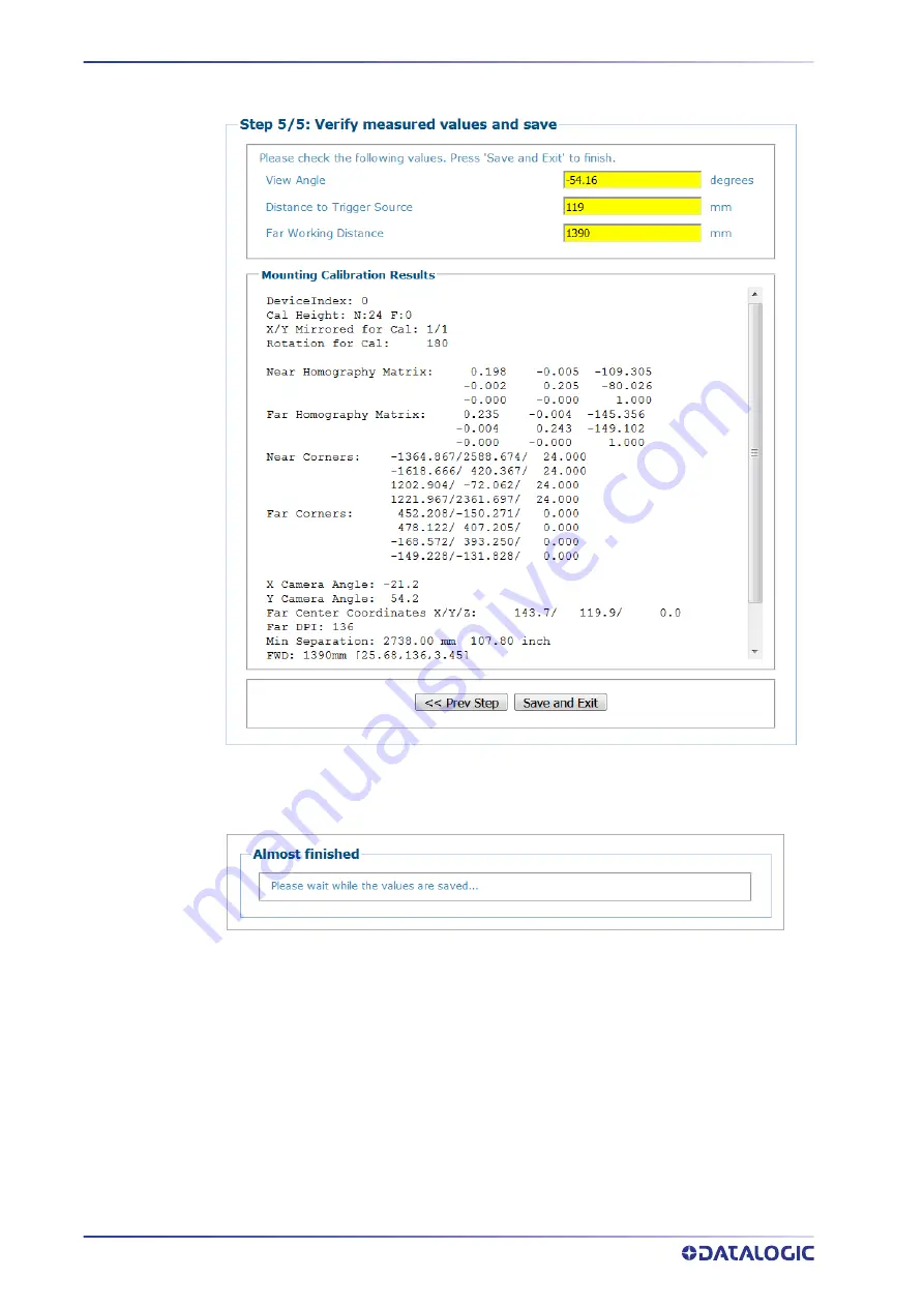
13. Click
Save and Exit
and the following message appears while the values are being
saved.
14. When the values have been saved e
‐
Genius will return to the Mounting screen for
that camera with the information learned from the Calibration Wizard in the
appropriate fields.
Содержание AV500
Страница 1: ...AV500 PRODUCT REFERENCE GUIDE 2D CAMERA...
Страница 53: ...MOUNTING PRODUCT REFERENCE GUIDE 33...
Страница 73: ...CBX510 CONNECTION BOX PRODUCT REFERENCE GUIDE 53 Photoelectric Sensor to CBX510 NPN...
Страница 74: ...ELECTRICAL INSTALLATION 54 AV500 2D CAMERA Photoelectric Sensor to CBX510 PNP...
Страница 84: ...ELECTRICAL INSTALLATION 64 AV500 2D CAMERA Photoelectric Sensor to CBX100 and CBX800 NPN...
Страница 86: ...ELECTRICAL INSTALLATION 66 AV500 2D CAMERA...
Страница 91: ...FOCUSING DEVICE WIRING PRODUCT REFERENCE GUIDE 71 Unpowered Outputs...
Страница 113: ...OPERATING MODE PRODUCT REFERENCE GUIDE 93...
Страница 203: ...PRODUCT REFERENCE GUIDE 183 12 Click Next Step and the following screen appears...
Страница 205: ...PRODUCT REFERENCE GUIDE 185...
Страница 218: ...E GENIUS 198 AV500 2D CAMERA...
Страница 230: ...E GENIUS 210 AV500 2D CAMERA...
Страница 231: ...PRODUCT REFERENCE GUIDE 211...
Страница 234: ...E GENIUS 214 AV500 2D CAMERA...
Страница 241: ...PRODUCT REFERENCE GUIDE 221 Click on Diagnostic Messages and a Diagnostic Messages window opens...
Страница 249: ...PRODUCT REFERENCE GUIDE 229...
Страница 253: ...PRODUCT REFERENCE GUIDE 233...
Страница 260: ...E GENIUS 240 AV500 2D CAMERA...
Страница 263: ...PRODUCT REFERENCE GUIDE 243 4 Select Auto Learn from the drop down and the following auto learn options appear...
Страница 266: ...E GENIUS 246 AV500 2D CAMERA...
Страница 299: ...AV500 CALIBRATION PRODUCT REFERENCE GUIDE 279...
Страница 321: ...NOTES...
Страница 322: ...NOTES...
Страница 323: ...NOTES...


