


GH DRIVER
6-
6
6.3.2 Relevant parameters of analog rigid tapping
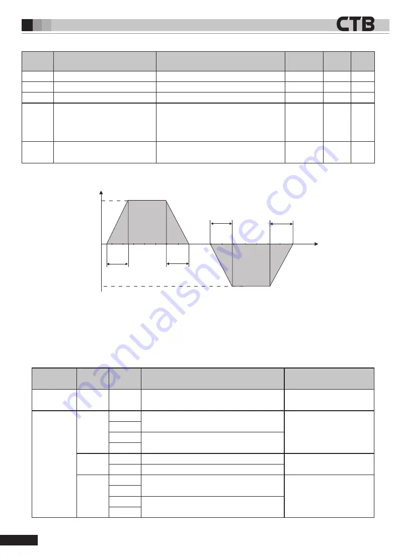
6.3.3 Acceleration and deceleration control curve
Function
parameter
Item
Description
Unit
Set range
Factory
setting
A3.30
maximum speed during rigid tapping set maximum speed of motor during rigid tapping
rpm
0~60000
1500
A3.31
acceleration time during rigid tapping Set acceleration time of motor during rigid tapping 0.01s/Krpm 0~20000
80
A3.32
deceleration time during rigid tapping set deceleration time of motor during rigid tapping 0.01s/Krpm 0~20000
80
A3.33
Speed ring proportiongain during
rigid tapping
set speed ring proportion gain during rigid
tapping, the value is higher, the gain is higher
and the rigidity is greater. Try to set large value
When the system does not produce oscillations.
-
0~65535
100
A3.34
speed ring integral time during rigid
tapping
set speed ring integral time Ti during rigid
tapping
,
the value is smaller, the rigidity is greater.
-
0~65535
40
Speed
Rotate
direction
Minus
rotate
direction
Time
A3.31
A3.31
A3.32
A3.32
6.4 Pulse rigid tapping /pulse position
6.4.1 Terminal definition and function parameters
Orthogonal pulse rigid tapping
Definition
Port
Signal
Function
Position control parameter
needs to be modified
Enable control
T3
I4
Forwardor/reverse rotation enabling (forward or
reverse is determined by direction of the pulse)
A2.19=1
Pulse input port
T2
PA+
Orthogonal Pulse phase A input
A2.17=1
A2.16=15
PA-
DB+
Orthogonal Pulse phase B input
DB-
T3
I11
24V High speed pulse phase A input
A2.17=2
A2.16=15
I12
24V High speed pulse phase B input
T4
SA+
Orthogonal Pulse phase A input
A2.17=0
A2.16=15
SA-
PB+
Orthogonal Pulse phase B input
PB-


