GH DRIVER
2K
FS
FI
FC
E
FV
FC
E
Speed command
GND
E
GH Servo driver
GH Servo driver
CNC System
2K
FS
FI
FC
E
FV
FC
E
Speed command
GND
E
GH Servo driver
GH Servo driver
CNC System
Wiring requirements
●
Connect to signal source or control signal with multi-core shielded cable or stranded shielded wire.
●
The near-end of shielding layer of the case (end near the driver) shall be connected to the connector housing.
●
During wiring, the control cables shall be arranged more than 30cm away from the main circuit and strong power line (including
power line, motor line, relay, contactor connecting cable), and avoid parallel layout. Vertical wiring is recommended to prevent
malfunction of the driver due to interference.
●
Filter magnetic ring provided by the manufacturer shall be used for long distance wiring. It shall be installed at the side near the
driver.
FV terminal wiring example
CNC system uses bipolar (-10V ~ +10 V) analog output. The speed is determined by the value of the analog, the direction of
rotation is determined by polarity of the analog as shown in Figure 2-16.
Signal
Function
Signal standard
FI
Unipolarity analog input terminal
A2-01=1
0~10V, input impedance: 20K
Ω
FV
Bipolarity analog input terminal
A2-01=0
-10V~+10V analog input,
input impedance: 20K
Ω
FS
inside provided speed setting power
DC10V, 50mA,
FC
analog common port
0V
E
Shielding layer connecting terminal
Wiring of analog input signal
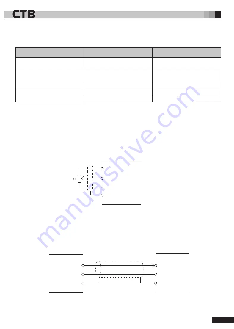
GH AC servo driver selects two analog input interfaces of FI and FV, as well as a group of power interface FS and FC for analog
input. Please see Table 2-13 for signal function description.
Figure 2-15 Conduct speed setting with internal power
Figure 2-16 Bipolar speed setting is conducted by CNC system
Table 2-13 Analog interface signal description
2-
19


