Chapter
5
Each component function
◆Digital I/O interface
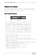
This interface controls digital I/O with two rows of six pins (JDIO1, JDIO2).
Among the eight DIO pins, two output pins (02, 03) are used for the user LED on the front.
The digital I/O interface is internally insulated.
Table 5.11 Digital I/O Connector
1
6
7
12
JDIO1
JDIO2
JDIO1
JDIO2
Pin No.
Signal
Pin No.
Signal
1
I0
7
O0
2
I1
8
O1
3
I2
9
O2 (Connected prohibition)
4
I3
10
O3 (Connected prohibition)
5
PWRON
11
COMPO
6
RST
12
COMPI
1)I0~I3 (JDIO1 Pin No. 1~4)
Input signal : You can input Input0, Input1, Input2, and Input3.
2)O0~O3 (JDIO2 Pin No. 7~10)
Output signal : You can output Onput0, Onput1, Onput2, and Onput3.
※You can not use Output2,3 because they are used for the user LED on the front.
3)PWRON,RST (JDIO1 Pin No.5,6)
Short-circuiting PWRON and GND or RST and GND triggers the same operation as pushing
the Power button or Reset button on the front.
※However, the power-supply from the outside is necessary.
4)COMPO,COMPI (JDIO2 Pin No.11,12)
These are used for the power-supply from the outside.
COMPO is GND and COMPI is VCC.
72
User’s Manual
Содержание VPC-2000
Страница 1: ...FA PC VPC Series VPC 2000 User s Manual CONTEC CO LTD...
Страница 2: ......
Страница 15: ...Chapter About the product Physical dimensions VPC 2000 mm Figure 2 1 VPC 2000 User s Manual 9...
Страница 18: ...Chapter About the product Motherboard Block chart Figure 2 4 Motherboard Block chart 12 User s Manual...
Страница 85: ...Chapter Software utirity 4 Language select Select a language and click Next 5 Setup Click Next User s Manual 79...
Страница 112: ...Chapter Software utirity 106 User s Manual...
Страница 122: ...Chapter Software RAID setup 3 Check Yes and select Next Input Name and Advanced arbitrarity 116 User s Manual...


