Chapter
3
Hardware setup
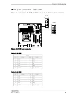
■Internal USB connector: USB5,6/USB9,10
Connectors for connecting the USB connector on the front panel of the case with an USB
extension bracket.
For the VPC-2000 series, the bracket is already connected to the USB connector on the
front panel by a special cable.
USB5,6
1
2
9
10
1
2
9
10
USB9,10
Figure 3.8 Internal USB Connector
Table 3.11 USB5,6/USB9,10
PIN
SIGNAL
PIN
SIGNAL
1
+5V
6
USB(6or10) +Data
2
+5V
7
GND
3
USB(5or9) -Data
8
GND
4
USB(6or10) -Data
9
Key (No Pin)
5
USB(5or9) +Data
10
NC
User’s Manual
27
Содержание VPC-2000
Страница 1: ...FA PC VPC Series VPC 2000 User s Manual CONTEC CO LTD...
Страница 2: ......
Страница 15: ...Chapter About the product Physical dimensions VPC 2000 mm Figure 2 1 VPC 2000 User s Manual 9...
Страница 18: ...Chapter About the product Motherboard Block chart Figure 2 4 Motherboard Block chart 12 User s Manual...
Страница 85: ...Chapter Software utirity 4 Language select Select a language and click Next 5 Setup Click Next User s Manual 79...
Страница 112: ...Chapter Software utirity 106 User s Manual...
Страница 122: ...Chapter Software RAID setup 3 Check Yes and select Next Input Name and Advanced arbitrarity 116 User s Manual...

