Chapter
3
Hardware setup
◆Mother board internal connector
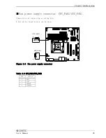
■ATX power-supply connector: EATXPWR1/ATX12V1
Connect the ATX power connector, observing the correct orientation.
24
12
1
13
EATXPWR1: ATX 24 pin connector
1
2
3
4
ATX12V1: ATX 12V power-supply connector
Figure 3.5 ATX power-supply connector
Table 3.7 EATXPWR1
PIN
SIGNAL
PIN
SIGNAL
1
+3.3V
13
+3.3V
2
+3.3V
14
-12V
3
GND
15
GND
4
+5V
16
PS_ON
5
GND
17
GND
6
+5V
18
GND
7
GND
19
GND
8
PW_OK
20
NC
9
5V_SB
21
+5V
10
+12V
22
+5V
11
+12V
23
+5V
12
+3.3V
24
GND
Table 3.8 ATX12V1
PIN
SIGNAL
1
+12V
2
GND
3
+12V
4
GND
Both EATXPWR1 and ATX12V1 are absolutely necessary power supplies for operation.
Turning on the power for only one of these may damage the system.
24
User’s Manual
Содержание VPC-2000
Страница 1: ...FA PC VPC Series VPC 2000 User s Manual CONTEC CO LTD...
Страница 2: ......
Страница 15: ...Chapter About the product Physical dimensions VPC 2000 mm Figure 2 1 VPC 2000 User s Manual 9...
Страница 18: ...Chapter About the product Motherboard Block chart Figure 2 4 Motherboard Block chart 12 User s Manual...
Страница 85: ...Chapter Software utirity 4 Language select Select a language and click Next 5 Setup Click Next User s Manual 79...
Страница 112: ...Chapter Software utirity 106 User s Manual...
Страница 122: ...Chapter Software RAID setup 3 Check Yes and select Next Input Name and Advanced arbitrarity 116 User s Manual...


