Chapter
3
Hardware setup
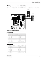
■COM port connector: COM3/COM4
These are connected to the COM3 and COM4 connectors at the rear of the main unit.
COM3
1
2
9
10
1
2
9
10
COM4
Figure 3.10 COM port connector
Table 3.13 COM3
RS-232C
PIN
SIGNAL
PIN
SIGNAL
1
DCD
6
CTS
2
DSR
7
DTR
3
SIN
8
RI
4
RTS
9
GND
5
SOUT
10
Key (No Pin)
Table 3.14 COM4
PIN
SIGNAL
PIN
SIGNAL
1
DCD
6
CTS
2
DSR
7
DTR
3
SIN
8
RI
4
RTS
9
GND
5
SOUT
10
Key (No Pin)
User’s Manual
29
Содержание VPC-2000
Страница 1: ...FA PC VPC Series VPC 2000 User s Manual CONTEC CO LTD...
Страница 2: ......
Страница 15: ...Chapter About the product Physical dimensions VPC 2000 mm Figure 2 1 VPC 2000 User s Manual 9...
Страница 18: ...Chapter About the product Motherboard Block chart Figure 2 4 Motherboard Block chart 12 User s Manual...
Страница 85: ...Chapter Software utirity 4 Language select Select a language and click Next 5 Setup Click Next User s Manual 79...
Страница 112: ...Chapter Software utirity 106 User s Manual...
Страница 122: ...Chapter Software RAID setup 3 Check Yes and select Next Input Name and Advanced arbitrarity 116 User s Manual...

