


9. Turn on external devices that are connected to the expansion base.
10. Be sure that A/B and C/D drive selection switches are correctly set
(Section C.3).
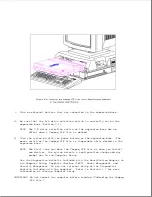
11. Turn the system on with the power switch on the computer or the power
switch on the expansion base.
NOTE: The first time you dock the Compaq LTE Elite in the expansion
base, you may be prompted to run Computer Setup to configure
optional devices.
The computer automatically detects and
configures many optional devices. In some instances you are
prompted to accept or reject a configuration change.
Follow the
instructions on the screen to change the system configuration.
Refer to Section 6.7 for more information on running Computer
Setup.
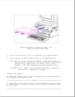
12. To turn off the computer (but remain docked) use one of the following
methods:
o Save and close open files, then turn off the power switch on the
expansion base or the power switch on the computer.
o Enter Shutdown at the DOS prompt or select Shutdown from the Compaq
Utilities group box within Microsoft Windows, then save open files
Содержание LTE Elite
Страница 139: ...6 Rotate the front edge of the keyboard up and lay it face down on the cloth covered display panel Figure 4 31 ...
Страница 140: ...7 Remove the hard drive security clips by gently lifting up on them Figure 4 32 ...
Страница 248: ...4 Remove the keylock from the outside of the bottom cover Figure 9 5 ...
Страница 249: ...5 Slide the plastic keylock barrel out of the bottom cover Figure 9 6 ...
Страница 258: ...6 Remove the power supply and bezel as an assembly by sliding it out of the rear of the expansion base Figure 9 15 ...
Страница 269: ...3 Disconnect the harness extension cable from the system board Figure 9 26 ...
Страница 279: ...5 Tighten the screws 6 Place the first end of the drive spacer 1 into the slot 2 of the first drive cage Figure 9 35 ...
Страница 297: ...5 Slide the switch board out of the switch frame Figure 9 52 ...
Страница 304: ...5 Replace the eject switch and screw Figure 9 59 ...
Страница 309: ...5 Replace the power switch and screw Figure 9 64 ...
Страница 319: ...Table A 5 Compaq LTE Elite Numeric Keypad Connector Pin Signal Pin Signal Ring Ground Tip Data Power ...
Страница 331: ...Table A 14 Compaq SmartStation Drive Power Connector Pin Signal Pin Signal 1 12V 4 Ground 2 Key 5 5V 3 Ground ...
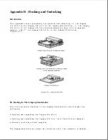
Страница 348: ...7 Unlock the expansion base keylock Figure D 3 ...
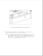
Страница 369: ...9 Push the lever toward the back of the convenience base Figure D 16 ...
Страница 373: ...5 Slide the computer toward you to remove it from the convenience base ...
Страница 387: ......


