


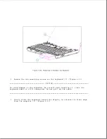


4.14 Power Interface Board (PIB)
To remove the power interface board (PIB), complete the following steps:
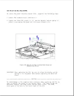
1. Remove the keyboard cover (Section 4.7).
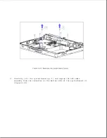
2. Remove the three PIB screws [1] [2] and the display switch spring [3],
which is secured by the back left PIB screw (Figure 4-35).
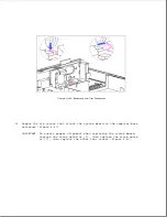
IMPORTANT: When replacing the PIB, be sure to align the display switch
spring in its alignment hole before replacing the back left
screw.
>>>>>>>>>>>>>>>>>>>>>>>>>>>>>>>>> CAUTION <<<<<<<<<<<<<<<<<<<<<<<<<<<<<<<<<
To avoid damage to the computer base enclosure when replacing the PIB, be
sure to install the screws in the correct holes.
The three screws are
different lengths (two long screws and one short screw). The short
screw goes in the hole in the front right of the PIB.
Содержание LTE Elite
Страница 139: ...6 Rotate the front edge of the keyboard up and lay it face down on the cloth covered display panel Figure 4 31 ...
Страница 140: ...7 Remove the hard drive security clips by gently lifting up on them Figure 4 32 ...
Страница 248: ...4 Remove the keylock from the outside of the bottom cover Figure 9 5 ...
Страница 249: ...5 Slide the plastic keylock barrel out of the bottom cover Figure 9 6 ...
Страница 258: ...6 Remove the power supply and bezel as an assembly by sliding it out of the rear of the expansion base Figure 9 15 ...
Страница 269: ...3 Disconnect the harness extension cable from the system board Figure 9 26 ...
Страница 279: ...5 Tighten the screws 6 Place the first end of the drive spacer 1 into the slot 2 of the first drive cage Figure 9 35 ...
Страница 297: ...5 Slide the switch board out of the switch frame Figure 9 52 ...
Страница 304: ...5 Replace the eject switch and screw Figure 9 59 ...
Страница 309: ...5 Replace the power switch and screw Figure 9 64 ...
Страница 319: ...Table A 5 Compaq LTE Elite Numeric Keypad Connector Pin Signal Pin Signal Ring Ground Tip Data Power ...
Страница 331: ...Table A 14 Compaq SmartStation Drive Power Connector Pin Signal Pin Signal 1 12V 4 Ground 2 Key 5 5V 3 Ground ...
Страница 348: ...7 Unlock the expansion base keylock Figure D 3 ...
Страница 369: ...9 Push the lever toward the back of the convenience base Figure D 16 ...
Страница 373: ...5 Slide the computer toward you to remove it from the convenience base ...
Страница 387: ......


