


o DC power to the computer when it is docked
o Ability to fast charge the battery pack in the computer whether the
expansion base is on or off
o Ability to fast charge an additional Compaq LTE Elite battery pack in the
SmartStation battery charging compartment
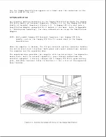
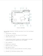
o Two full-sized slots for 8- or 16-bit Industry Standard Architecture
(ISA) expansion boards
o Two internal half-height drive bays
o Ability to start a docked Compaq LTE Elite computer from the computer's
hard drive or from an IDE hard drive in the expansion base
o An integrated SCSI-2 controller that supports up to seven SCSI-2 devices,
including one internal SCSI-2 drive
o An integrated Ethernet controller (with RJ-45 and AUI connectors)
o The following standard external device connectors:
- PS/2 mouse
- External keyboard (enhanced 101/102-key)
- External monitor
- Serial (RS-232C compliant)
- SCSI-2
- Ethernet AUI (IEEE 802.3 10BASE5 or 10BASE2 with optional Thinnet
Coax Transceiver)
- Ethernet RJ-45 (IEEE 802.3 10BASE-T)
- Parallel
NOTE: The parallel port is Centronics compatible, EPP 1.9 compliant,
when the Compaq LTE Elite is docked.
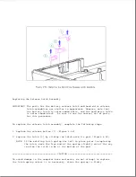
o A removable monitor support cover capable of supporting an external
monitor weighing up to 55 lb (25 kg)
o Horizontal guides, keylock assembly, and override blocker for securing
the computer to the expansion base
o Provision for an optional cable lock for securing the expansion base to a
stationary object
o Ability to use power conservation mode for IDE hard drives and Energy
Star compliant monitors (when used with Compaq LTE Elite computer only)
Содержание LTE Elite
Страница 139: ...6 Rotate the front edge of the keyboard up and lay it face down on the cloth covered display panel Figure 4 31 ...
Страница 140: ...7 Remove the hard drive security clips by gently lifting up on them Figure 4 32 ...
Страница 248: ...4 Remove the keylock from the outside of the bottom cover Figure 9 5 ...
Страница 249: ...5 Slide the plastic keylock barrel out of the bottom cover Figure 9 6 ...
Страница 258: ...6 Remove the power supply and bezel as an assembly by sliding it out of the rear of the expansion base Figure 9 15 ...
Страница 269: ...3 Disconnect the harness extension cable from the system board Figure 9 26 ...
Страница 279: ...5 Tighten the screws 6 Place the first end of the drive spacer 1 into the slot 2 of the first drive cage Figure 9 35 ...
Страница 297: ...5 Slide the switch board out of the switch frame Figure 9 52 ...
Страница 304: ...5 Replace the eject switch and screw Figure 9 59 ...
Страница 309: ...5 Replace the power switch and screw Figure 9 64 ...
Страница 319: ...Table A 5 Compaq LTE Elite Numeric Keypad Connector Pin Signal Pin Signal Ring Ground Tip Data Power ...
Страница 331: ...Table A 14 Compaq SmartStation Drive Power Connector Pin Signal Pin Signal 1 12V 4 Ground 2 Key 5 5V 3 Ground ...
Страница 348: ...7 Unlock the expansion base keylock Figure D 3 ...
Страница 369: ...9 Push the lever toward the back of the convenience base Figure D 16 ...
Страница 373: ...5 Slide the computer toward you to remove it from the convenience base ...
Страница 387: ......


