


Screws
>>>>>>>>>>>>>>>>>>>>>>>>>>>>>>>>> CAUTION <<<<<<<<<<<<<<<<<<<<<<<<<<<<<<<<<
Screws in the unit are not interchangeable. Damage may occur if you insert
an incorrect screw. As you remove screws, place them with the component you
removed to help avoid error.
>>>>>>>>>>>>>>>>>>>>>>>>>>>>>>>>>>>>><<<<<<<<<<<<<<<<<<<<<<<<<<<<<<<<<<<<<<
Plastics
Use care when handling the plastic case and housing assemblies, as they can
be damaged from excessive force during assembly and disassembly.
>>>>>>>>>>>>>>>>>>>>>>>>>>>>>>>>> CAUTION <<<<<<<<<<<<<<<<<<<<<<<<<<<<<<<<<
Plated plastic surfaces require special handling to ensure that they are
not scratched. Scratches may flake the plated material, contaminate the
electronics, and cause system failure.
>>>>>>>>>>>>>>>>>>>>>>>>>>>>>>>>>>>>><<<<<<<<<<<<<<<<<<<<<<<<<<<<<<<<<<<<<<
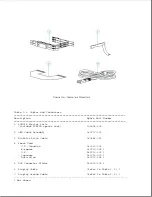
4.2 Required Tools And Software
The following tools and software are required to service the computer:
o Torx T-8 screwdriver
o 3/16-inch nut driver (for screwlocks)
o Pair of needle-nosed pliers
o Compaq trackball removal tool (Table 3-13)
o Connector removal tool (Table 3-13)
o Display bezel removal tool (Table 3-13)
o Compaq diagnostics diskette
NOTE: Most of the screws in the computer are slotted Torx T-8 type, which
can be removed and replaced with a Torx T-8 or flat-bladed
screwdriver.
4.3 Removal And Replacement List
The following list outlines the removal and replacement procedures covered
in this chapter:
4.4 Preparation procedures for removal and replacement
4.5 Battery pack
4.6 Memory expansion board
4.7 Keyboard cover
4.8 Auxiliary battery
4.9 Display assembly
- Display bezel
- Display panel
- Inverter board
- Trackball board
Содержание LTE Elite
Страница 139: ...6 Rotate the front edge of the keyboard up and lay it face down on the cloth covered display panel Figure 4 31 ...
Страница 140: ...7 Remove the hard drive security clips by gently lifting up on them Figure 4 32 ...
Страница 248: ...4 Remove the keylock from the outside of the bottom cover Figure 9 5 ...
Страница 249: ...5 Slide the plastic keylock barrel out of the bottom cover Figure 9 6 ...
Страница 258: ...6 Remove the power supply and bezel as an assembly by sliding it out of the rear of the expansion base Figure 9 15 ...
Страница 269: ...3 Disconnect the harness extension cable from the system board Figure 9 26 ...
Страница 279: ...5 Tighten the screws 6 Place the first end of the drive spacer 1 into the slot 2 of the first drive cage Figure 9 35 ...
Страница 297: ...5 Slide the switch board out of the switch frame Figure 9 52 ...
Страница 304: ...5 Replace the eject switch and screw Figure 9 59 ...
Страница 309: ...5 Replace the power switch and screw Figure 9 64 ...
Страница 319: ...Table A 5 Compaq LTE Elite Numeric Keypad Connector Pin Signal Pin Signal Ring Ground Tip Data Power ...
Страница 331: ...Table A 14 Compaq SmartStation Drive Power Connector Pin Signal Pin Signal 1 12V 4 Ground 2 Key 5 5V 3 Ground ...
Страница 348: ...7 Unlock the expansion base keylock Figure D 3 ...
Страница 369: ...9 Push the lever toward the back of the convenience base Figure D 16 ...
Страница 373: ...5 Slide the computer toward you to remove it from the convenience base ...
Страница 387: ......


