


are proper. ** If the
outputs are not
proper, replace the
expansion base system
board.
---------------------------------------------------------------------------
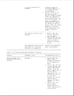
The motor starts to
There is a physical
Undock the computer
engage, but the
obstruction.
by pressing the eject
computer does not
button. If the
completely undock and
computer does not
a beep is emitted.
undock, remove the
computer using the
manual eject override
method (Section D.1),
and complete the
following steps as
required:
1. Check that the
docking mechanism
sled can move
freely back and
forth. If there is
resistance, make
sure that the sled
is clean and free
of foreign
substances.
2. Ensure that the
bottom of the
computer and the
surface of the
expansion base
docking bay are
clean.
3. Ensure that the
rubber feet are
properly located
on the bottom of
the computer.
4. Gently shake the
expansion base
upside down and
listen for any
loose objects.
---------------------------------------------------------------------------
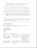
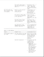
** The voltage outputs for the motor cable's red and white wires vary
according to the state of the motor, as follows:
When the motor is turning forward, the red wire is + 18V and the white
wire is 0V.
When the motor is turning backward, the red wire is 0V and the white
wire is + 18V.
When the motor is not turning, the red wire is + 18V and the white
wire is + 18.
===========================================================================
Problem
Probable Cause
Recommended Action(s)
===========================================================================
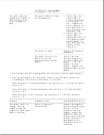
The top cover is bowing
Check for bowing in
Содержание LTE Elite
Страница 139: ...6 Rotate the front edge of the keyboard up and lay it face down on the cloth covered display panel Figure 4 31 ...
Страница 140: ...7 Remove the hard drive security clips by gently lifting up on them Figure 4 32 ...
Страница 248: ...4 Remove the keylock from the outside of the bottom cover Figure 9 5 ...
Страница 249: ...5 Slide the plastic keylock barrel out of the bottom cover Figure 9 6 ...
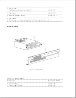
Страница 258: ...6 Remove the power supply and bezel as an assembly by sliding it out of the rear of the expansion base Figure 9 15 ...
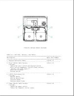
Страница 269: ...3 Disconnect the harness extension cable from the system board Figure 9 26 ...
Страница 279: ...5 Tighten the screws 6 Place the first end of the drive spacer 1 into the slot 2 of the first drive cage Figure 9 35 ...
Страница 297: ...5 Slide the switch board out of the switch frame Figure 9 52 ...
Страница 304: ...5 Replace the eject switch and screw Figure 9 59 ...
Страница 309: ...5 Replace the power switch and screw Figure 9 64 ...
Страница 319: ...Table A 5 Compaq LTE Elite Numeric Keypad Connector Pin Signal Pin Signal Ring Ground Tip Data Power ...
Страница 331: ...Table A 14 Compaq SmartStation Drive Power Connector Pin Signal Pin Signal 1 12V 4 Ground 2 Key 5 5V 3 Ground ...
Страница 348: ...7 Unlock the expansion base keylock Figure D 3 ...
Страница 369: ...9 Push the lever toward the back of the convenience base Figure D 16 ...
Страница 373: ...5 Slide the computer toward you to remove it from the convenience base ...
Страница 387: ......


