


NOTE: To replace the inverter board on the 9.5-inch color TFT model,
replace the entire display assembly (refer to "Removing the Display
Assembly" in this section).
It is not necessary to remove the display assembly from the system unit to
remove the display inverter board. To remove the display inverter board,
complete the following steps:
1. Remove the display bezel (refer to "Display Bezel" in this section).
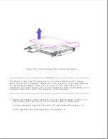
2. Remove the backlight cable from the inverter board (Figure 4-13).
3. Remove the display cable [1] from the inverter board (Figure 4-17).
4. Remove the two screws [2] that attach the display inverter board to the
display enclosure (Figure 4-17).
5. Remove the inverter board (Figure 4-17).
IMPORTANT: In order to line up the screws properly when replacing the
inverter board, be sure that the alignment hole in the inverter
board
is
properly
seated
over
the
alignment
post
in
the
display
enclosure.
Содержание LTE Elite
Страница 139: ...6 Rotate the front edge of the keyboard up and lay it face down on the cloth covered display panel Figure 4 31 ...
Страница 140: ...7 Remove the hard drive security clips by gently lifting up on them Figure 4 32 ...
Страница 248: ...4 Remove the keylock from the outside of the bottom cover Figure 9 5 ...
Страница 249: ...5 Slide the plastic keylock barrel out of the bottom cover Figure 9 6 ...
Страница 258: ...6 Remove the power supply and bezel as an assembly by sliding it out of the rear of the expansion base Figure 9 15 ...
Страница 269: ...3 Disconnect the harness extension cable from the system board Figure 9 26 ...
Страница 279: ...5 Tighten the screws 6 Place the first end of the drive spacer 1 into the slot 2 of the first drive cage Figure 9 35 ...
Страница 297: ...5 Slide the switch board out of the switch frame Figure 9 52 ...
Страница 304: ...5 Replace the eject switch and screw Figure 9 59 ...
Страница 309: ...5 Replace the power switch and screw Figure 9 64 ...
Страница 319: ...Table A 5 Compaq LTE Elite Numeric Keypad Connector Pin Signal Pin Signal Ring Ground Tip Data Power ...
Страница 331: ...Table A 14 Compaq SmartStation Drive Power Connector Pin Signal Pin Signal 1 12V 4 Ground 2 Key 5 5V 3 Ground ...
Страница 348: ...7 Unlock the expansion base keylock Figure D 3 ...
Страница 369: ...9 Push the lever toward the back of the convenience base Figure D 16 ...
Страница 373: ...5 Slide the computer toward you to remove it from the convenience base ...
Страница 387: ......


