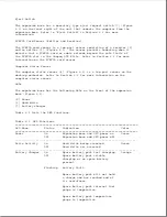


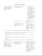


"backplane board") and the system board (also known as the "interconnect
board") each have a printed description of where the drive cables connect.
Each drive cable also has a printed description, a Compaq spare part
number, and a Compaq assembly part number. Refer to Section 9.15 for more
information on drive cable locations.
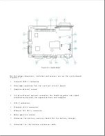
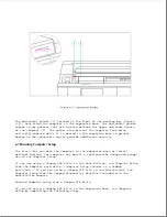
Power Switch Cable Harness
The power switch cable harness [7] (Figure 6-15) runs from the power switch
[8] to the harness extension cable on the system board [1] and includes the
following:
o Power switch and its soldered cable
o Cables for the computer status sensor
o Connectors for the PCMCIA card sensor (emitter and receiver)
o Power and hard drive LEDs (integrated into the power switch board)
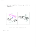
Power Switch
The momentary type power switch [8] (Figure 6-15) provides power to the
main expansion base circuits if it is pressed after a computer is docked
(refer to "Power Supply" in this section).
The power switch is connected to the power switch cable harness and is
composed of the power switch board and small mechanical parts.
The small
mechanical parts (button, spring, frame, and light pipes) can also be
replaced separately using parts from the Miscellaneous Small Mechanical
Parts Kit (Table 8-8).
NOTE: The power switch board is integrated into the power switch cable
harness. To replace the power switch board, the power switch cable
harness must be replaced (refer to Section 9.17).
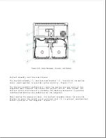
Eject Switch Cable Harness
The eject switch cable harness [3] runs from the eject switch [4] to the
harness extension cable on the system board [1] (Figure 6-15) and includes
the following:
o Eject switch and its soldered cable
o Keylock switch and its soldered cable
o Battery charger LED (integrated into the eject switch board)
Eject Switch
The momentary type eject switch [4] (Figure 6-15) undocks the computer from
the expansion base after certain conditions are met (Appendix D).
The eject switch is connected to the eject switch cable harness and is
composed of the eject switch board and small mechanical parts.
The small
mechanical parts (button, spring, frame, and light pipes) can also be
Содержание LTE Elite
Страница 139: ...6 Rotate the front edge of the keyboard up and lay it face down on the cloth covered display panel Figure 4 31 ...
Страница 140: ...7 Remove the hard drive security clips by gently lifting up on them Figure 4 32 ...
Страница 248: ...4 Remove the keylock from the outside of the bottom cover Figure 9 5 ...
Страница 249: ...5 Slide the plastic keylock barrel out of the bottom cover Figure 9 6 ...
Страница 258: ...6 Remove the power supply and bezel as an assembly by sliding it out of the rear of the expansion base Figure 9 15 ...
Страница 269: ...3 Disconnect the harness extension cable from the system board Figure 9 26 ...
Страница 279: ...5 Tighten the screws 6 Place the first end of the drive spacer 1 into the slot 2 of the first drive cage Figure 9 35 ...
Страница 297: ...5 Slide the switch board out of the switch frame Figure 9 52 ...
Страница 304: ...5 Replace the eject switch and screw Figure 9 59 ...
Страница 309: ...5 Replace the power switch and screw Figure 9 64 ...
Страница 319: ...Table A 5 Compaq LTE Elite Numeric Keypad Connector Pin Signal Pin Signal Ring Ground Tip Data Power ...
Страница 331: ...Table A 14 Compaq SmartStation Drive Power Connector Pin Signal Pin Signal 1 12V 4 Ground 2 Key 5 5V 3 Ground ...
Страница 348: ...7 Unlock the expansion base keylock Figure D 3 ...
Страница 369: ...9 Push the lever toward the back of the convenience base Figure D 16 ...
Страница 373: ...5 Slide the computer toward you to remove it from the convenience base ...
Страница 387: ......


