


Power/
On
Power on
LED on top of unit
Green
standby
Flashing
Standby
(active when display is
open). Identical LED on
front of unit (active
when display is closed).
---------------------------------------------------------------------------
Battery
On
Battery
Front of unit
Orange
State
charging
Flashing
LowBatt 1
at one
per
second
Flashing
LowBatt 2
at two
per
second
---------------------------------------------------------------------------
Hard Drive
On
Hard drive
Front of unit
Green
Activity
being
accessed
---------------------------------------------------------------------------
Diskette
On
Diskette
Front of unit
Green
Drive
drive being
Activity
accessed
---------------------------------------------------------------------------
Scroll
On
Scroll lock
Top of unit
Green
Lock
selected
---------------------------------------------------------------------------
Caps Lock
On
Caps lock
Top of unit
Green
selected
---------------------------------------------------------------------------
Num Lock
On
Num lock
Top of unit
Green
selected
===========================================================================
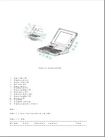
Display Switch
The computer has a display switch mounted on the power interface board
(PIB) located near the display hinge. When the display is closed, this
switch activates the front-mounted power/standby LED and simultaneously
deactivates the display and the top-mounted LEDs.
Trackball
The computer has an integrated PS/2 style trackball located on the display
bezel. The trackball is disabled whenever an external mouse is connected to
the keyboard/mouse connector. The trackball buttons are located on the back
side of the display.
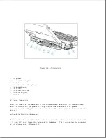
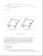
1.5 Connectors
This section covers the I/O pass-through connectors on the computer
(Figure 1-4). Refer to Appendix A for connector pin assignments.
Содержание LTE Elite
Страница 139: ...6 Rotate the front edge of the keyboard up and lay it face down on the cloth covered display panel Figure 4 31 ...
Страница 140: ...7 Remove the hard drive security clips by gently lifting up on them Figure 4 32 ...
Страница 248: ...4 Remove the keylock from the outside of the bottom cover Figure 9 5 ...
Страница 249: ...5 Slide the plastic keylock barrel out of the bottom cover Figure 9 6 ...
Страница 258: ...6 Remove the power supply and bezel as an assembly by sliding it out of the rear of the expansion base Figure 9 15 ...
Страница 269: ...3 Disconnect the harness extension cable from the system board Figure 9 26 ...
Страница 279: ...5 Tighten the screws 6 Place the first end of the drive spacer 1 into the slot 2 of the first drive cage Figure 9 35 ...
Страница 297: ...5 Slide the switch board out of the switch frame Figure 9 52 ...
Страница 304: ...5 Replace the eject switch and screw Figure 9 59 ...
Страница 309: ...5 Replace the power switch and screw Figure 9 64 ...
Страница 319: ...Table A 5 Compaq LTE Elite Numeric Keypad Connector Pin Signal Pin Signal Ring Ground Tip Data Power ...
Страница 331: ...Table A 14 Compaq SmartStation Drive Power Connector Pin Signal Pin Signal 1 12V 4 Ground 2 Key 5 5V 3 Ground ...
Страница 348: ...7 Unlock the expansion base keylock Figure D 3 ...
Страница 369: ...9 Push the lever toward the back of the convenience base Figure D 16 ...
Страница 373: ...5 Slide the computer toward you to remove it from the convenience base ...
Страница 387: ......


