


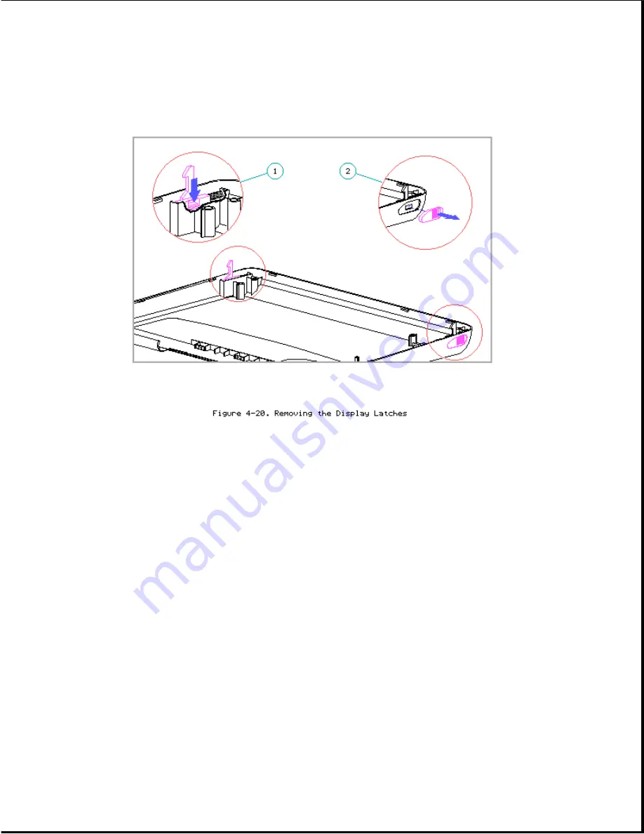
3. Remove the display latches and springs from the latch compartments.
Display Clutches
To remove the display clutches, complete the following steps:
1. Remove the keyboard cover (Section 4.7).
2. Remove the display assembly (refer to "Removing the Display Assembly" in
this section).
3. Remove the display bezel (refer to "Display Bezel" in this section).
NOTE: Two screws that attach the bezel to the display enclosure also
attach the clutches to the display enclosure.
IMPORTANT: Before removing the two remaining clutch screws (step 4),
note that these screws also attach the mounting tab of the
trackball shield [2] and one of the mounting tabs of the
display ground cable [3] (Figure 4-21).
The tab for the
display ground cable goes beneath the clutch. The tab for the
trackball shield goes either above or beneath the clutch,
depending on which type of shield was originally installed in
Содержание LTE Elite
Страница 139: ...6 Rotate the front edge of the keyboard up and lay it face down on the cloth covered display panel Figure 4 31 ...
Страница 140: ...7 Remove the hard drive security clips by gently lifting up on them Figure 4 32 ...
Страница 248: ...4 Remove the keylock from the outside of the bottom cover Figure 9 5 ...
Страница 249: ...5 Slide the plastic keylock barrel out of the bottom cover Figure 9 6 ...
Страница 258: ...6 Remove the power supply and bezel as an assembly by sliding it out of the rear of the expansion base Figure 9 15 ...
Страница 269: ...3 Disconnect the harness extension cable from the system board Figure 9 26 ...
Страница 279: ...5 Tighten the screws 6 Place the first end of the drive spacer 1 into the slot 2 of the first drive cage Figure 9 35 ...
Страница 297: ...5 Slide the switch board out of the switch frame Figure 9 52 ...
Страница 304: ...5 Replace the eject switch and screw Figure 9 59 ...
Страница 309: ...5 Replace the power switch and screw Figure 9 64 ...
Страница 319: ...Table A 5 Compaq LTE Elite Numeric Keypad Connector Pin Signal Pin Signal Ring Ground Tip Data Power ...
Страница 331: ...Table A 14 Compaq SmartStation Drive Power Connector Pin Signal Pin Signal 1 12V 4 Ground 2 Key 5 5V 3 Ground ...
Страница 348: ...7 Unlock the expansion base keylock Figure D 3 ...
Страница 369: ...9 Push the lever toward the back of the convenience base Figure D 16 ...
Страница 373: ...5 Slide the computer toward you to remove it from the convenience base ...
Страница 387: ......


