


NOTE: The 75 MHz processor is also available as an upgrade option.
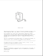
Temperature Sensors
The primary temperature sensor is located on the processor board and the
secondary temperature sensor is located on the system board. These sensors
turn the fan on when the system approaches maximum reliable operating
temperatures.
If the temperature continues to rise, a system management interrupt (SMI)
is generated that creates a pop-up window (depicting a thermometer) to warn
the user of the temperature overload and the unit goes into Standby within
several seconds. If the temperature continues to rise, the computer turns
itself off.
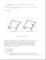
NOTE: The temperature sensors are integrated into the processor board and
the system board. To replace a temperature sensor, the appropriate
board must be replaced.
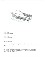
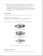
Power Interface Board (PIB)
The power interface board (PIB) (Figure 1-8) is mounted to the system board
by a 16-pin connector. The PIB provides the following features:
Содержание LTE Elite
Страница 139: ...6 Rotate the front edge of the keyboard up and lay it face down on the cloth covered display panel Figure 4 31 ...
Страница 140: ...7 Remove the hard drive security clips by gently lifting up on them Figure 4 32 ...
Страница 248: ...4 Remove the keylock from the outside of the bottom cover Figure 9 5 ...
Страница 249: ...5 Slide the plastic keylock barrel out of the bottom cover Figure 9 6 ...
Страница 258: ...6 Remove the power supply and bezel as an assembly by sliding it out of the rear of the expansion base Figure 9 15 ...
Страница 269: ...3 Disconnect the harness extension cable from the system board Figure 9 26 ...
Страница 279: ...5 Tighten the screws 6 Place the first end of the drive spacer 1 into the slot 2 of the first drive cage Figure 9 35 ...
Страница 297: ...5 Slide the switch board out of the switch frame Figure 9 52 ...
Страница 304: ...5 Replace the eject switch and screw Figure 9 59 ...
Страница 309: ...5 Replace the power switch and screw Figure 9 64 ...
Страница 319: ...Table A 5 Compaq LTE Elite Numeric Keypad Connector Pin Signal Pin Signal Ring Ground Tip Data Power ...
Страница 331: ...Table A 14 Compaq SmartStation Drive Power Connector Pin Signal Pin Signal 1 12V 4 Ground 2 Key 5 5V 3 Ground ...
Страница 348: ...7 Unlock the expansion base keylock Figure D 3 ...
Страница 369: ...9 Push the lever toward the back of the convenience base Figure D 16 ...
Страница 373: ...5 Slide the computer toward you to remove it from the convenience base ...
Страница 387: ......


