background image

CompAir UK Ltd 

5280D Compressor Publication 98407.1440


Page 46


1440.doc 


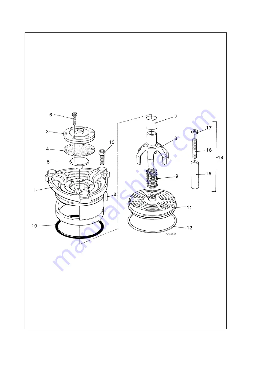
SUCTION VALVE COVER

Содержание 5280D.1.IAC

Страница 1: ...MBERS on nameplate PUBLICATION NUMBER 98407 1440 ISSUE DATE MARCH 2006 CUSTOMER ORDER NUMBER CompAir UK Ltd Reavell House White House Road IPSWICH ENGLAND IP1 5PB Telephone 44 0 1473 242000 Fax 44 0 1...

Страница 2: ...PRESSURE BAR PSI SERVICE PLAN NUMBER REMARKS SEE OVER FOR MORE SIGNED 100 1 2 3 2000 4000 8000 12000 16000 20000 24000 28000 32000 36000 40000 44000 48000 52000 56000 60000 64000 68000 72000 76000 800...

Страница 3: ...DATE REMARKS DATE REMARKS logsheet5280 d...

Страница 4: ...9 Operation 23 10 Maintenance 27 11 Fault Finding 31 Appendix 1 Illustrations 35 General Arrangement Typical A41043 P I Diagram Typical E46786 Electrical Wiring Diagram Typical compressor only D71419...

Страница 5: ...ssembly E61065 Main Air Gas System A30137 Control Drain Parts E61776 Cooling Water Piping Parts A30138 Gauge Panel Parts E61775 Liner Extraction Parts C203267 Service Tools C203268 Appendix 4 Service...

Страница 6: ...ied recommended or approved by CompAir UK Ltd or the failure to maintain this equipment in accordance with the maintenance instructions may invalidate the WARRANTY cause equipment failure create unsaf...

Страница 7: ...DETAILS Contact Name Sales Telephone 44 0 1473 602222 Address CompAir UK Ltd Reavell Ranelagh Road Ipswich IP2 0AQ ENGLAND Notes Telephone 44 0 1473 602222 Fax 44 0 1473 601704 Contact Names Parts Tel...

Страница 8: ...this Manual is retained with the compressor for reference and should remain with the compressor if it is sold or transferred to another user Ensure that the new user is made fully aware of the need t...

Страница 9: ...CompAir UK Ltd 5280D Compressor Publication 98407 1440 Page 6 1440 doc...

Страница 10: ...07 1440 Page 7 1440 doc 4 SAFETY PROCEDURES Page General 9 Warnings Cautions and Notes 9 General Safety Precautions 9 Installation Precautions 10 Operational Precautions 10 Maintenance and Repair Prec...

Страница 11: ...r approved by CompAir UK Ltd may lead to failures in service which would not be covered by warranty Any unauthorised modifications or failure to maintain this equipment in accordance with maintenance...

Страница 12: ...made unsafe and that there is no risk to persons or property Failure to observe these precautions given under Safety Precautions may be considered dangerous practice or misuse of the compressor Read a...

Страница 13: ...ty devices guards or insulation fitted In order to limit the risk of Legionnaires Disease CompAir UK LTD advise caution with the use of cooling towers for water cooling the compressor Closed circuit o...

Страница 14: ...aterial will decompose Degraded Viton gives off Hydrogen Fluoride fumes and if in contact with the skin an acid formed causes severe burns If Viton seals appear charred or gummy do not touch with unpr...

Страница 15: ...no pollution to any drain or natural water course and that no burning of waste takes place which could cause pollution of the atmosphere Keep the compressor clean at all times Protect components and e...

Страница 16: ...in the crankcase wall at the non drive end A gear type oil pump driven directly from the crankshaft draws oil from the sump and forces it through a micro filter element filter filtered oil passes thro...

Страница 17: ...and delivery valves are of large diameter annular multiport low lift plate type The valves combine a large flow area with low lift resulting in low air speed and quiet operation Valves fitted to secon...

Страница 18: ...220 mm Cylinder bore third stage 185 mm 6 5 LUBRICATION Crankcase sump capacity 50 litres Recommended oils mineral Shell Corena P100 or Mobil Rarus 427 Recommended oils synthetic Reavellite 6 6 OPERAT...

Страница 19: ...1 5 Condensate discharge RP 2 6 11 SETTING ADJUSTMENTS Switching Thermometer Settings SETTINGS C Compressor Operating Pressure First stage Second stage Third stage Final Delivery Up to 50 bar g 180 1...

Страница 20: ...crete base an extra 300 mm minimum all round the compression unit baseframe and typically a minimum depth 450 mm Please note this depth will depend upon the soil sub base and should be confirmed by a...

Страница 21: ...complete isolation from the building or other equipment is required mount the compressor and drive motor etc on a common baseframe carried on anti vibration mounts Include a pipework vibration elimina...

Страница 22: ...pework between compressor and air receiver as short as possible and do not reduce the diameter below the size of the unit delivery flange This also applies to the flange sizes of any ancillary equipme...

Страница 23: ...d against corrosion for an extended period Oil free units are stored with desiccant included Similarly any compressor taken out of service must be protected against corrosion The rate at which storage...

Страница 24: ...e made Remove the hand pump and reconnect the pressure oil gauge pipe Refit all access doors ensure that the securing bolts are tightened to the specified torque Remove the oil filler cap from the lef...

Страница 25: ...at the isolator and remove fuses 8 2 8 Connect air delivery manifold flange to user s pipework or air receiver 8 2 9 Remove crankcase doors and crosshead access doors to inspect bearings for signs of...

Страница 26: ...ut the following before starting a compressor which has been out of operation for more than 6 months Ensure the power supply is OFF and no pressurised air has remained in the compression unit or assoc...

Страница 27: ...ntinues to pass receiver air at a reduced pressure to a water control valve keeping the valve open This valve supplies cooling water to the cylinders and cylinder heads whenever the compressor is runn...

Страница 28: ...tion or should the oil pressure fall below a minimum pre set pressure The compressor can be STOPPED manually by depressing the EMERGENCY STOP button When the compressor has stopped by fault indicating...

Страница 29: ...CompAir UK Ltd 5280D Compressor Publication 98407 1440 Page 26 1440 doc...

Страница 30: ...of damage and security of fittings 10 1 3 Recording Pressures and Temperatures Maintain a daily record of operating pressures and temperatures including the ambient temperature Take the readings when...

Страница 31: ...e manufacturers recommendations 10 2 2 Maintenance Schedule SEE RSP 5280D for Schedule details SEE ALSO TORQUE WRENCH SETTING Page 32 10 3 MAINTENANCE PROCEDURES 10 3 1 Oil circuit Change crankcase oi...

Страница 32: ...nd Stg Cooler Cover float end to cooler body M12 95 Bursting Disc Covers M10 55 3rd Stg Cooler Cover fixed end to cooler body M12 95 3rd Stg Cooler Cover fixed end to cooler body M20 460 3rd Stg Coole...

Страница 33: ...CompAir UK Ltd 5280D Compressor Publication 98407 1440 Page 30 1440 doc...

Страница 34: ...igation please ensure Cooling water temperature rise across the machine and flow rate are correct Direction of rotation is correct Lubricating oil is at correct level Compressor servicing is up to dat...

Страница 35: ...of the pressure switch Remove and test operation Replace as necessary 11 2 On Starting electric motor hums Motor single phasing Check voltage on all three phases For START DELTA starting STAR time too...

Страница 36: ...y 11 8 Compressor will not unload automatically Solenoid valve manually overridden Return valve to automatic operation mode Leak on diaphragm drain valves Check drain valves for leak tight operation f...

Страница 37: ...ew with CompAir recommended oil 11 15 High oil consumption Check piston rod gland wear Entrained air when unloaded Check by manually operating interstage safety valves Loose flywheel or pulley Check k...

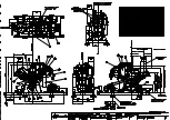
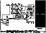
Страница 38: ...d 5280D Compressor Publication 98407 1440 Page 35 1440 doc Appendix 1 Drawings Wiring Diagrams General Arrangement Typical A41043 P I Diagram Typical E46786 Electrical Wiring Diagram Typical compresso...

Страница 39: ......

Страница 40: ......

Страница 41: ......

Страница 42: ...CompAir UK Ltd 5280D Compressor Publication 98407 1440 Page 36 1440 doc...

Страница 43: ...2 41 Crankcase 3 43 First Stage Cylinder 45 First Stage Suction Valve Cover 47 First Stage Delivery Valve Cover 49 First State Suction Delivery Valves 51 Crankshaft Connecting Rods 53 First Stage Cros...

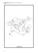
Страница 44: ...CompAir UK Ltd 5280D Compressor Publication 98407 1440 Page 38 1440 doc CRANKCASE 1...

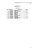
Страница 45: ...CRIPTION No OFF 1 C20010 55 CRANKCASE 1 2 C10190 85 DOOR 1 3 C10190 101 JOINT 1 4 A4341 100 CAPSCREW 8 5 C10190 86 FILLER 1 7 C10190 105 JOINT 1 8 A4333 96 HEX HD SCREW 2 9 C10190 115 RIGHT FOOT 1 10...

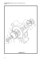
Страница 46: ...CompAir UK Ltd 5280D Compressor Publication 98407 1440 Page 40 1440 doc CRANKCASE 2...

Страница 47: ...TION No OFF C20010 55 CRANKCASE 1 1 C10190 87 CROSSHEAD COVER 2 2 C10190 102 JOINT 2 3 A42341 39 CAPSCREW 16 9 A3803 69 DRAIN COCK 1 10 95410 285 SOCKET 1 11 95404 800 HEX NIPPLE 1 12 C10190 84 CRANKC...

Страница 48: ...CompAir UK Ltd 5280D Compressor Publication 98407 1440 Page 42 1440 doc CRANKCASE 3...

Страница 49: ...010 55 CRANKCASE 1 1 C10190 63 BEARING HOUSING 1 2 C20010 47 BEARING HOUSING 1 3 C10190 98 JOINT 2 4 C10530 315 RETAINER 2 5 C10190 588 MAIN BEARING 3 6 C10190 590 WASHER 2 7 A6450 104 OIL SEAL 1 8 C1...

Страница 50: ...CompAir UK Ltd 5280D Compressor Publication 98407 1440 Page 44 1440 doc CYLINDER 1st STAGE...

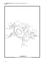
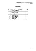
Страница 51: ...0000 3 CYLINDER HEAD 1 3 C20000 11 CYLINDER HEAD JOINT 1 4 A3764 7 PLUG 1 5 95405 858 HEX BUSH 1 6 A4341 132 CAPSCREW 12 7 C11582 1 CAPSCREW 4 8 C10500 191 LINER 1 9 A1413 576 PIN 1 10 C20010 70 PIN L...

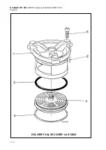
Страница 52: ...CompAir UK Ltd 5280D Compressor Publication 98407 1440 Page 46 1440 doc SUCTION VALVE COVER...

Страница 53: ...VALVE RETAINER 4 4 C20000 37 DIAPHRAGM 4 5 C20021 36 DIAPHRAGM FOLLOWER 4 6 A4341 13 CAPSCREW 24 7 A10218 16 BEARING BUSH 4 8 C20001 25 UNLOADER FORK 4 9 C20021 28 UNLOADER FORK SPRING 4 10 A10252 43...

Страница 54: ...CompAir UK Ltd 5280D Compressor Publication 98407 1440 Page 48 1440 doc DELIVERY VALVE COVER 1st STAGE...

Страница 55: ...Page 49 1440 doc DELIVERY VALVE COVER 1st STAGE PARTS LIST REF No PART No DESCRIPTION No OFF 1 C20000 6 DELIVERY VALVE COVER 4 2 A1475 100 LOCATING PIN 4 3 A10347 13 O RING 4 4 C11304 204 DELIVERY VA...

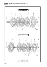
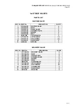
Страница 56: ...CompAir UK Ltd 5280D Compressor Publication 98407 1440 Page 50 1st STAGE VALVES DELIVERY VALVE SUCTION VALVE 1440 doc...

Страница 57: ...4 7 95515 262 LOCATING PIN 4 8 C11304 152 LIFT WASHER 12 9 C11304 157 COIL SPRING 24 10 C11304 211 CASTLE NUT 4 11 A3762 46 SPIT PIN 4 DELIVERY VALVE REF No PART No DESCRIPTION No OFF 1 C11304 204 DEL...

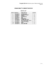
Страница 58: ...CompAir UK Ltd 5280D Compressor Publication 98407 1440 Page 52 1440 doc CRANKSHAFT CONNECTING ROD...

Страница 59: ...RT No DESCRIPTION No OFF 1 C10190 754 CRANKSHAFT 1 2 C10500 217 BALANCE WEIGHT 2 3 C10500 167 SCREW 4 4 C10190 32 LOCKING PIN 8 5 C10190 333 KEY 1 6 C20010 38 DRIVING PIN 2 7 C10190 208 CONNECTING ROD...

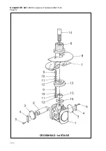
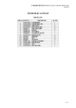
Страница 60: ...CompAir UK Ltd 5280D Compressor Publication 98407 1440 Page 54 1440 doc CROSSHEAD 1st STAGE...

Страница 61: ...0190 636 CROSSHEAD PIN 1 3 C10190 287 END PLATE 2 4 C10190 332 LOCKING PLATE 2 5 A4333 91 HEX HD SCREW 8 6 C20001 11 GLAND 1 7 C20000 20 OIL SHIELD 1 8 C20000 21 OIL BAFFLE PLATE 1 9 C10190 415 GLAND...

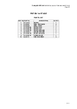
Страница 62: ...CompAir UK Ltd 5280D Compressor Publication 98407 1440 Page 56 1440 doc PISTON 1st STAGE...

Страница 63: ...ST REF No PART No DESCRIPTION No OFF 1 C11321 8 PISTON 1 2 C20040 1 RING PRESSURE 2 3 C20040 2 RING GUIDE 1 4 C10190 698 PISTON ROD 1 5 C10190 700 PISTON NUT 1 6 C10190 704 PISTON WASHER 1 7 A10300 18...

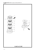
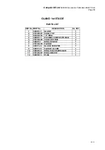
Страница 64: ...CompAir UK Ltd 5280D Compressor Publication 98407 1440 Page 58 1440 doc GLAND 1st STAGE...

Страница 65: ...N No OFF 1 C20001 11 GLAND 1 2 C10190 657 CAGE TOP 1 3 A10252 236 O RING 1 4 C20001 13 PACKING COMPOSITE PAIR 3 5 C10190 658 CAGR BOTTOM 2 6 C20001 4 RING SPACER 1 7 C10190 659 FLANGE 1 8 C20011 22 GL...

Страница 66: ...CompAir UK Ltd 5280D Compressor Publication 98407 1440 Page 60 1440 doc OIL PUMP...

Страница 67: ...6 PLATE BLANKING 1 11 C20010 43 LUBRICATOR JOINT 1 12 A4341 76 CAPSCREW 4 13 A4322 4 NUT 4 14 A6738 54 WASHER SHAKEPROOF 4 15 C20010 30 GEAR HOUSING COVER 1 16 C20010 42 GEAR HOUSING JOINT 2 17 A4341...

Страница 68: ...CompAir UK Ltd 5280D Compressor Publication 98407 1440 Page 62 1440 doc OIL PUMP FILTER...

Страница 69: ...NIPPLE 1 30 C20010 83 OIL FILTER ADAPTOR 1 31 A4341 51 CAPSCREW 3 32 A6454 132 PLUG 1 33 98504 65 JOINT 1 34 C20010 40 FILTER DISTANCE PIECE 1 35 C20010 44 FILTER DISTANCE JOINT 1 36 A4341 53 CAPSCREW...

Страница 70: ...CompAir UK Ltd 5280D Compressor Publication 98407 1440 Page 64 1440 doc INTERCOOLER...

Страница 71: ...LER 1 6 C20010 8 BOTTOM COVER 1 7 C20010 14 JOINT 1 8 A4335 51 HEX HD SCREW 8 9 A4335 53 SCREW 4 10 C11003 12 COVER JOINT 1 11 C11003 8 INNER HEAD COVER 1 12 C11003 7 COVER JOINT 1 13 A4334 204 HEX HD...

Страница 72: ...CompAir UK Ltd 5280D Compressor Publication 98407 1440 Page 66 1440 doc 1st STAGE PIPE WORK...

Страница 73: ...ion 98407 1440 Page 67 1440 doc 1st STAGE PIPE WORK PART LIST REF No PART No DESCRIPTION No OFF 1 C20011 6 1st STAGE AIR PIPE 1 2 A1641 500 62 1st SAFETY VALVE 1 4 C20010 16 JOINT 1 5 C20010 15 INTERC...

Страница 74: ...CompAir UK Ltd 5280D Compressor Publication 98407 1440 Page 68 1440 doc...

Страница 75: ...y E61316 Second Third Stage Cylinder Assembly A30136 Second Stage Cooler Assembly E61066 Third Stage Cooler Assembly E61065 Main Air Gas System A30137 Control Drain Parts E61776 Cooling Water Piping P...

Страница 76: ......

Страница 77: ......

Страница 78: ......

Страница 79: ......

Страница 80: ......

Страница 81: ......

Страница 82: ......

Страница 83: ......

Страница 84: ......

Страница 85: ......

Страница 86: ...CompAir UK Ltd 5280D Compressor Publication 98407 1440 Page 70 1440 doc...

Страница 87: ...CompAir UK Ltd 5280D Compressor Publication 98407 1440 Page 71 1440 doc Appendix 4 Service Plan...

Страница 88: ...s Check for leaks operation of D D V s Check condition of all ancillaries FIRST 2000 HOURS SERVICE Check condition of 1st 2nd 3rd stage cylinder bores RSP5280DM 3 Change oil filter Change suction filt...

Страница 89: ...1 C201839 Check and clean separator strainers drain lines Check belt drive for alignment and tension Adjust as necessary Check for oil air leaks Check tightness of all fasteners Check for leaks operat...

Страница 90: ...20000 37 2nd 3rd stage suction valve unloader diaphragm 2 98650 1782 Connecting rod bolt 4 C10190 29 Connecting rod nut 4 C10190 266 Connecting rod washer 4 C10190 30 Check and clean separator straine...

Страница 91: ...s drain lines Check belt drive for alignment and tension Adjust as necessary Check for oil air leaks Check tightness of all fasteners Check for leaks operation of D D V s Check condition of all ancill...

Страница 92: ...il filter 1 98262 199 Suction filter element 1 98262 1019 Bursting disc kit 1 C201556 100 Service kit 1st stage valve 1 98650 2007 Service kit 2nd stage valve 1 98650 1827 3rd stage piston ring kit 1...

Страница 93: ...nternal oil pipe for security Check safety valves setting Check internal cleanliness of drive motor Check starter contacts for arcing and pitting Check inter stage cooler tubes for internal fouling or...

Страница 94: ...CompAir UK Ltd 5280D Compressor Publication 98407 1440 Page 72 1440 doc...

Страница 95: ...07 1440 Page 73 1440 doc Appendix 5 Ancillary Parts PET Scan Controller APP408 Anti vibration Mounts APP004 Pressure Gauge APP070 Safety Valve APP167 Diaphragm Drain Valve APP202 Solenoid Valve APP138...

Страница 96: ...nameplate PUBLICATION NUMBER APP 408C ISSUE DATE JANUARY 2004 CUSTOMER ORDER NUMBER CompAir UK Ltd Ranelagh Road IPSWICH ENGLAND IP2 0AQ Telephone 44 0 1473 602222 Fax 44 0 1473 601704 Parts Fax 44 0...

Страница 97: ...hine Configuration 10 2 2 6 Regulating Settings 10 2 2 7 Factory Settings 11 2 2 7 1 Typical Compressor Settings 13 2 2 8 Service Settings 13 2 2 9 Diagnostics 13 2 2 9 1 Test Digital Inputs 14 2 2 9...

Страница 98: ...App 408 Customer PET controller installation guide user s manual Page 2 App 408C 98155 1015...

Страница 99: ...splayed The other display normally shows the status of compressor but will display warning and trip faults if they occur All the analogue pressure and temperature readings hours run time to service tr...

Страница 100: ...Push buttons The controller is equipped with 8 tactile push buttons and each push button has its own specific function Button Function Arrow up Select previous menu item Arrow down Select next menu i...

Страница 101: ...enu code entry parameter modification This paragraph explains how to select a menu and how to scroll through the different parameters 2 1 1 Entering menus Reset and or returning to the basic menu Sele...

Страница 102: ...ion Error list Timer list Parameters Sub menus Main selection Machine config Regulating settings Factory settings Service settings Diagnostics Parameters Parameters Parameters Parameters Test digital...

Страница 103: ...r button step 4 Step 1 Step 2 and step 4 Step 3 b Parameter modification with password protection The parameters of several menus are protected by a password With the following procedure those paramet...

Страница 104: ...available but waiting for system pressure to drop before starting 2 2 2 Error log menu The Controller saves the 10 most recent occurred faults By using the up and down arrow button all the messages c...

Страница 105: ...ull load 40bar 20bar Pressur e unload level 0 5 bar P schedule Enabling or disabling the pressure schedule OFF OFF ON Press schedule The current time can be set as well as the configuration of the pre...

Страница 106: ...Selection between local load unload control or remote load unload control through a digital input In remote unload will unload compressor and load will give normal control by system pressure LOC LOC R...

Страница 107: ...ow this pressure 15 bar 0 16 bar 3 rd stage high pressure The high pressure limit for the 3 rd stage on which the compressor is shut down 44 bar 0 50 bar 3 rd stage low pressure The low pressure limit...

Страница 108: ...0s Unloaded run time The unloaded run time is the time that the motor keeps on running after the stop button has been pushed This is to release condensate before the compressor stops 60s 1s 120s Blowd...

Страница 109: ...gs 1 st stage delivery 185 215 210 215 2 nd stage delivery 155 175 195 200 3 rd stage delivery 175 190 200 200 Final delivery 50 55 55 55 Water temperature 60 60 60 Drain times normal ambients Open se...

Страница 110: ...1 2 2 9 2 Test digital outputs Warning the relays are being powered for testing Digital output No Parameter Function Min Max 1 Main contactor control relay Relay 1 is powered Off On 2 Star contactor c...

Страница 111: ...very temperature The applied voltage of the analogue input 7 is displayed 0 5 volts 8 Final air delivery temperature The applied voltage of the analogue input 8 is displayed 0 5 volts 9 1 st stage pre...

Страница 112: ...ature 15 C 15 C 3 rd stage dely temp 3 rd stage temperature offset setting Trimming the sensor compared with the real measured temperature 15 C 15 C Final air dely temp Final air temperature offset se...

Страница 113: ...the need for fitting a link if a trip is not fitted However if a trip is fitted then it should be operated in the NC mode and the corresponding digital input changed to NC The water flow is also opti...

Страница 114: ...ms Table 19 2 4 Menu structure quick reference Basic menu Date time Ready to start Standby Starting busy Offload On load 50 Stop busy Blowing down Warning and alarms High pressure H High temperature H...

Страница 115: ...L REMOTE Pressure control LOCAL REMOTE Machine number for RS485 Regulating settings for proportional control Entry code 11 P factor I factor Factory settings DEF fault delay time Oil pressure Oil Pres...

Страница 116: ...tages of 42 2V peak or more the unit is classified as class III equipment Although in this situation safety earth is not needed it is still necessary to earth the unit to fulfil the electromagnetic co...

Страница 117: ...App 408C 2 7 Fusing 2 fuses of 1 6A slow must be used for protection of the secondary winding of the transformer and they must be able to withstand 20A rms during at least 10ms The controller is equi...

Страница 118: ...Operating temperature IEC 68 2 2B IEC 68 2 14 Na IEC 68 2 14 Nb IEC 68 2 3 Ca IEC 68 2 1 A 10 C 55 C Storage temperature IEC 68 2 1 A IEC 68 2 2 B 25 C 65 C Rel humidity at 40C at front side 95 Rel h...

Страница 119: ...on usage i e regular usage every 3 months Note This dimension may only change a small amount during the life of the mount approximately 2mm 4 Any oil or paint contact with the rubber mount will affec...

Страница 120: ...CompAir UK Ltd APP 004 ANTI VIBRATION MOUNTS Page 2 app004 doc...

Страница 121: ...ld be made to remove a pressurised gauge The pressure system must be totally relieved if the gauge can not be isolated otherwise The remainder of the pressure medium contained in the element may be ha...

Страница 122: ...CompAir UK Ltd PUBLICATION APP070 PRESSURE GAUGES GENERAL Page 2 app070 doc...

Страница 123: ...e discharge pipe should not be less than the area of the safety valve outlet Where safety valves are discharged into a manifold the manifold must be capable of accommodating simultaneous discharge of...

Страница 124: ...cked 98650 1164 is the base unit number 98650 1164 28 28 being to the setting in bar g wire locked 98650 1163 is the base unit number 98650 1163 7 6 7 6 being to the setting in bar g wire locked 98650...

Страница 125: ...Setscrew 95000 228 8 6 Valve Plate C201978 3 7 Screw Csk 95028 112 3 8 Seal PS1322 6 3 9 Back Nut PS1290 4 3 10 Safety Valve 98650 1011 1 11 Washer 98660 1157 1 12 Stud D66720 10 45 2 13 Valve Seat C...

Страница 126: ...casing vessel and then into a suitable receptacle On start up the solenoid valve re opens and as the pressure builds up the valves close and the cycle repeats itself on shutdown For continuous running...

Страница 127: ...N Technical Details Current consumption Part No Voltage Hz Current Inrush Hold PS2197 1 230 50 AC 26 VA 16 VA PS2197 2 110 50 AC 26 VA 16 VA PS2197 3 220 60 AC 26 VA 16 VA PS2197 4 110 60 AC 26 VA 16...

Страница 128: ...CompAir UK Ltd PUBLICATION APP 138 3 WAY SOLENOID VALVES PS2197 Page 2 app138 doc...

Страница 129: ...ty stream can force dirt into the spaces between windings etc Grease removing solvents should only be used very sparingly so as not to damage impregnating varnish or insulation Bearings are charged wi...

Страница 130: ...CompAir UK PUBLICATION APP034 ELECTRIC MOTOR MAINTENANCE GENERAL Page 2 APP034 doc...

Страница 131: ...s taking care not to trap fingers Tension belts to 1 25 setting forces see table 1 Run drive under load for 15 20 minutes Stop and check tension reset to basic value If problems are experienced with b...

Страница 132: ...t the upper marker ring against the bottom edge of the top tube 5 Place the belt tension indicator on top of the belt at the centre of span and apply a force at right angles to the belt deflecting it...

Страница 133: ...CompAir UK Ltd 5280D Compressor Publication 98407 1440 Page 74 1440 doc...

Страница 134: ...d has no control Such hazardous conditions may lead to accidents that can be life threatening cause substantial bodily injury or result in damage to the equipment CompAir UK Ltd can bear no responsibi...

Отзывы: