


CompAir UK Ltd
5280D Compressor Publication 98407.1440
Page 13
1440.doc
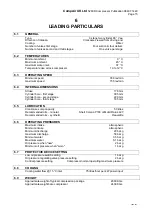
5
GENERAL DESCRIPTION
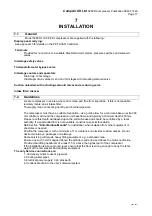
5.1 INTRODUCTION
The 5000 Series water-cooled compressors are heavy duty, reciprocating air and gas compressors.
The 5280 D model being a three stage design with two cylinders arranged in a 90 degree Vee configuration Whilst the
first stage is double acting, the second and third stages cylinders are a tandem single acting piston.
This model delivers oil free compressed air. The oil used to lubricate the running gear is excluded from the cylinders by
alternative style piston rod glands in distance pieces between the crankcase and cylinders.
Air is drawn into the compressor intake to the first stage cylinder, compressed on both up and down stoke of this double
acting piston before being cooled and any moisture separated, and passed to the second stage where the air is
compressed again.
The second stage delivers air through a pulsation damper to a cooler and a separator to the third stage where it is
compressed to a maximum pressure of 50 bar g. Delivered third stage air follows a similar route through a pulsation
damper, cooler and separator before finally delivered to the system via a non return valve.
Cylinder lubrication for all three stages is achieved with polytetrafluorethylene (PTFE) piston rings.
The small end of the connecting rod is carried on a gudgeon pin retained in the crosshead by end plates.
Cast iron cylinders are carried on a single piece cast iron crankcase which has two access doors. All gas or air passages
and a cooling water jacket are embodied in the cylinder and cylinder head castings.
Aluminium pistons are used throughout. Each piston being secured by a nut to the piston rod.
The lower end of the piston rod is attached to a crosshead moving in a guide sleeve.
5.1.1 LUBRICATION
Running Gear
Oil is contained in the sump which is filled through a port in one of the crankcase doors. The correct oil level is indicated
on a dipstick housed in the crankcase wall at the non-drive end.
A gear type oil pump, driven directly from the crankshaft, draws oil from the sump and forces it through a micro-filter
element filter. filtered oil passes through internal drillings to the main end bearing at the non-drive end and then through
drilled holes in the crankshaft to the big-end bearings. A pipe carries the oil to the main end bearings.
Drillings in the connecting rods and crosshead carry oil to the small end bushes and crosshead guides. Oil drains back
under gravity to the sump.
Oil pressure is controlled by an adjustable relief valve in the side of the filter housing. The valve opens when oil pressure
reaches a pre-set level and relieves excess pressure by allowing oil to return to the sump.
A switch in the oil feed pipe to the drive-end bearings operates to stop the compressor if the oil pressure falls below a
pre-set value.
Dry Cylinders
The 5280D is an oil-free unit and has dry cylinders and lubrication of the cylinder walls is provided by PTFE rings.
5.2 COOLING
SYSTEM
Cooling water is circulated to cylinder water jackets and cylinder heads and interstage heat exchangers. The first stage
intercooler consists of a cast iron barrel design within which is a bundle of spirally wound copper tubes. The air flows
through these and the cooling water over before entry to the second stage cylinder for further compression. Second and
third stage or final cooler, allow the air to pass thorough the tubes and the water over to effect controlled cooling between
each stage.
PULSATION / SEPARATOR VESSELS
Separators are installed after each inter-stage cooler to remove condensate from the air. An automatic condensate drain
at the base of the separator allows moisture collected in the first stage to be drained to a collection vessel or surge tank.
The second and third stages separators are connected directly to the diaphragm condensate drain connections on the
Universal Drain Valve (UDS) unit. Condensate from all stages is simultaneously drained at timed intervals or when ever
the compressor stops. Automatic operation of this Drain Unit on stopping also ensures the compressor is unloaded ready
for starting.
Содержание 5280D.1.IAC
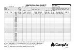
Страница 3: ...DATE REMARKS DATE REMARKS logsheet5280 d...
Страница 9: ...CompAir UK Ltd 5280D Compressor Publication 98407 1440 Page 6 1440 doc...
Страница 29: ...CompAir UK Ltd 5280D Compressor Publication 98407 1440 Page 26 1440 doc...
Страница 33: ...CompAir UK Ltd 5280D Compressor Publication 98407 1440 Page 30 1440 doc...
Страница 39: ......
Страница 40: ......
Страница 41: ......
Страница 42: ...CompAir UK Ltd 5280D Compressor Publication 98407 1440 Page 36 1440 doc...
Страница 44: ...CompAir UK Ltd 5280D Compressor Publication 98407 1440 Page 38 1440 doc CRANKCASE 1...
Страница 46: ...CompAir UK Ltd 5280D Compressor Publication 98407 1440 Page 40 1440 doc CRANKCASE 2...
Страница 48: ...CompAir UK Ltd 5280D Compressor Publication 98407 1440 Page 42 1440 doc CRANKCASE 3...
Страница 50: ...CompAir UK Ltd 5280D Compressor Publication 98407 1440 Page 44 1440 doc CYLINDER 1st STAGE...
Страница 52: ...CompAir UK Ltd 5280D Compressor Publication 98407 1440 Page 46 1440 doc SUCTION VALVE COVER...
Страница 54: ...CompAir UK Ltd 5280D Compressor Publication 98407 1440 Page 48 1440 doc DELIVERY VALVE COVER 1st STAGE...
Страница 58: ...CompAir UK Ltd 5280D Compressor Publication 98407 1440 Page 52 1440 doc CRANKSHAFT CONNECTING ROD...
Страница 60: ...CompAir UK Ltd 5280D Compressor Publication 98407 1440 Page 54 1440 doc CROSSHEAD 1st STAGE...
Страница 62: ...CompAir UK Ltd 5280D Compressor Publication 98407 1440 Page 56 1440 doc PISTON 1st STAGE...
Страница 64: ...CompAir UK Ltd 5280D Compressor Publication 98407 1440 Page 58 1440 doc GLAND 1st STAGE...
Страница 66: ...CompAir UK Ltd 5280D Compressor Publication 98407 1440 Page 60 1440 doc OIL PUMP...
Страница 68: ...CompAir UK Ltd 5280D Compressor Publication 98407 1440 Page 62 1440 doc OIL PUMP FILTER...
Страница 70: ...CompAir UK Ltd 5280D Compressor Publication 98407 1440 Page 64 1440 doc INTERCOOLER...
Страница 72: ...CompAir UK Ltd 5280D Compressor Publication 98407 1440 Page 66 1440 doc 1st STAGE PIPE WORK...
Страница 74: ...CompAir UK Ltd 5280D Compressor Publication 98407 1440 Page 68 1440 doc...
Страница 76: ......
Страница 77: ......
Страница 78: ......
Страница 79: ......
Страница 80: ......
Страница 81: ......
Страница 82: ......
Страница 83: ......
Страница 84: ......
Страница 85: ......
Страница 86: ...CompAir UK Ltd 5280D Compressor Publication 98407 1440 Page 70 1440 doc...
Страница 87: ...CompAir UK Ltd 5280D Compressor Publication 98407 1440 Page 71 1440 doc Appendix 4 Service Plan...
Страница 94: ...CompAir UK Ltd 5280D Compressor Publication 98407 1440 Page 72 1440 doc...
Страница 98: ...App 408 Customer PET controller installation guide user s manual Page 2 App 408C 98155 1015...
Страница 120: ...CompAir UK Ltd APP 004 ANTI VIBRATION MOUNTS Page 2 app004 doc...
Страница 122: ...CompAir UK Ltd PUBLICATION APP070 PRESSURE GAUGES GENERAL Page 2 app070 doc...
Страница 128: ...CompAir UK Ltd PUBLICATION APP 138 3 WAY SOLENOID VALVES PS2197 Page 2 app138 doc...
Страница 130: ...CompAir UK PUBLICATION APP034 ELECTRIC MOTOR MAINTENANCE GENERAL Page 2 APP034 doc...
Страница 133: ...CompAir UK Ltd 5280D Compressor Publication 98407 1440 Page 74 1440 doc...


