M0201ANC_uc
CommScope Era
™
Fiber Low Power Carrier Access Point Installation Guide
© June 2019 CommScope, Inc.
Page 55
Connect the Cables to the Fiber CAP L
C
ONNECT
THE
C
ABLES
TO
THE
F
IBER
CAP L
Complete the following procedures in the order in which they are presented. Unless otherwise noted, each
procedure is applicable to a singular Fiber CAP L (not in a cascade), or to a Primary or Secondary CAP L in a
cascade.
•
"Ground the Fiber CAP L (Optional)” on page 55
•
"Connect the Passive RF Antenna” on page 59
•
"Connect the Fiber CAP L to a Classic CAN or TEN” on page 60
•
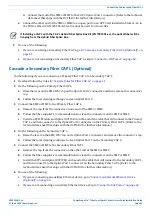
"Cascade a Secondary Fiber CAP L (Optional)” on page 61
•
"Connect an External Ethernet Device (Optional)” on page 62
•
"Connect to Vdc Power” on page 62
.
Do not remove protective caps from any of the connectors until instructed to do so.
Ground the Fiber CAP L (Optional)
Follow the steps below to ground the OPA only if grounding is required in your locality or if the installation
plans require the CAP L be grounded. The different CAP L installation procedures will tell you when to ground
the CAP L.
The CAP L is equipped with an M6 grounding stud located on the back of the unit; however, grounding is
not necessary. CAP Ls are classified as low-voltage devices and do not have internal power supplies.
CommScope recommends checking your local and national electrical codes to determine if grounding is
a requirement.
Do the following to ground a Fiber CAP L.
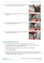
1
Obtain a length of #18 AWG (1.00 mm) insulated stranded copper wire for use as a chassis-grounding
wire.
2
Terminate one end of the wire with a ring terminal.
3
Locate the chassis-ground stud at the rear of the enclosure.
4
Remove the Keps nut from the chassis-ground stud.
Содержание Era
Страница 1: ...CommScope Era Fiber Low Power Carrier Access Point Installation Guide M0201ANC_uc June 2019 ...
Страница 71: ......


