CommScope Era
™
Fiber Low Power Carrier Access Point Installation Guide
M0201ANC_uc
Page 40
© June 2019 CommScope, Inc.
Mount the Fiber CAP L
2
Insert a 16 AWG (1.31 mm
2
) 3-conductor AC input cable through the cable gland in the junction box.
A plenum rated AC input cable is required when using the Plenum AC Power Supply kit or else the cable
must be routed to the junction box in conduit.
3
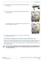
Terminate the cables using WAGO 221 Series Lever-Nuts or equivalent connectors as shown in
.
WAGO 221 SERIES LEVER-NUTS OR EQUIV.
(5 mm)
SEE CONNECTION DIAGRAM AT RIGHT.
AC INPUT CABLE
POWER
SUPPLY
Figure 16.
AC/DC Supply Cable Terminations
4
Torque the cable gland nut to 3.0 Nm (26.5 in-lb) to secure the cable.
5
Replace the junction box cover and tighten the four Phillips head screws to secure it.
6
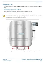
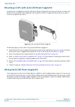
Mount the AC/DC Power Supply Kit to the CAP L mounting bracket.
Due to derating requirements, each CAP L must have its own PSU – no sharing is permitted.
7
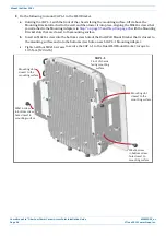
Assemble and mount the AC/DC Power Supply Kit and the CAP L, as described below and as shown in
(CAP L with Fan Kit). The Local
Power Jumper Cable Assembly will be connected to the AC/DC Power Supply Junction Box at the factory.
a
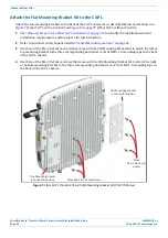
Use the four screws to attach the AC/DC Power Supply assembly to the Wall Mounting Bracket.
b
Attach the assembled AC/DC Power Supply Kit and Wall Mounting Bracket to the selected mounting
location.
c
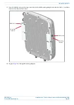
Use the six M6-1.0 x14mm screws to attach the two Angled Mounting Brackets to the Wall Mounting
Bracket.
i
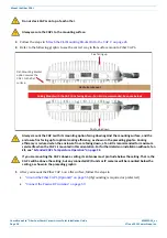
Put the top two flange-head screws halfway into the mounting brackets, and then use them to
“hang” the CAP L in the Wall Mounting Bracket.
ii
Attach the bottom two flange-head screws.
iii
Tighten all four screws.
Содержание Era
Страница 1: ...CommScope Era Fiber Low Power Carrier Access Point Installation Guide M0201ANC_uc June 2019 ...
Страница 71: ......

