CLASSIC BLAST MACHINE with TLR-100/300 REMOTE CONTROLS
Page 4
© 2018 CLEMCO INDUSTRIES CORP.
www.clemcoindustries.com
Manual No. 22501, Rev. I 02/18
system "fails to safe", which means when an interruption
in the control-air circuit occurs for reasons such as a
break in the line, the compressor stops running, or if the
operator drops the blast hose, the remote control
deactivates the blast machine and blasting stops.
1.4.3.3
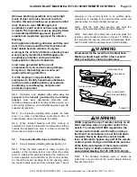
Components of the TLR remote control system
are shown in Figures 1 and 2. They include the inlet
valve piston or diaphragm outlet valve (the piston valve
is used in most applications, the diaphragm valve is
recommended for use with fine mesh or aggressive
abrasive), RLX control handle, 50-ft. and 5-ft. long
twinline control hoses, 2 control hose unions, and an 18-
inch-long interconnecting hose.
1.4.3.4
TLR remote controls are pressure-release-style
systems, which control the pressurization and
depressurization of the blast machine. Pressurization,
which starts blasting, occurs when the control handle is
pressed, and depressurization, which stops blasting,
occurs when the handle is released.
WARNING
Moist air that freezes can cause blockage at the
control handle or in the control lines. Blockage
can cause involuntary activation of the remote
controls or prevent the controls from
deactivating upon release of the control handle.
This situation can result in serious injury or
death. If remote controls are operated in
freezing or near-freezing weather, install a
Clemco Antifreeze Injector, stock no. 05537, on
the remote control air-supply line.
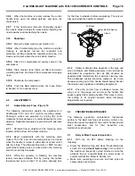
1.4.3.5
Clemco remote controls operate pneumatically
on a return-air principle. A stream of control air travels
from the orifice on the inlet valve, down the outbound
twinline (shown shaded
1
in Figure 2) and escapes
through the opening located under the control handle
lever. The normally closed inlet valve remains closed,
and the normally open outlet valve remains open. As
long as air escapes through the handle’s opening, the
remote control system remains inactive. When the
Figure 2
1
Shading indicates the outbound line; it does not matter which side of the twinline is used for the outbound and return line
When using a regulator to reduce
blast pressure, relocate the orifice
upstream of the regulator and plug
the orifice port in the inlet valve.
Piston Outlet Valve
Pressure Regulator
Orifice Fitting
Diaphragm Outlet Valve
5-Ft. Twinline Hose (Outbound side)
RLX Control Handle
Muffler (accessory)
not included with the remote
control system.
3/16" x 18-Inch Hose
Safety Petcock
Elbow Adaptor
Compressed-Air Inlet
Twinline Hose Unions (2)
50-Ft. Twinline Hose
(Inbound side of twinline)
Orifice Fitting
1/16" orifice as seen
from backside of fitting


