CLASSIC BLAST MACHINE with TLR-100/300 REMOTE CONTROLS
Page 22
© 2018 CLEMCO INDUSTRIES CORP.
www.clemcoindustries.com
Manual No. 22501, Rev. I 02/18
6.5.1
All service on the outlet valve must be done with
the air OFF and the air supply locked out and tagged
out. It is not necessary to remove the valve from the
blast machine.
6.5.2
Remove the cap by unscrewing the four cap
screws.
6.5.3
Remove the diaphragm and inspect it for
damage. Replace as necessary.
6.5.4
Inspect the seat in the body. If worn, replace the
body.
6.5.5
Reassemble in reverse order.
6.6
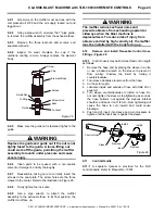
Abrasive Trap - Figure 21
WARNING
To avoid serious injury from the sudden release
of compressed air, all service on the blast
machine must be done with the air OFF and the
air supply locked out and tagged out and the air-
supply line bled.
NOTE: Failure to clean the abrasive trap on a regular
basis is a major cause of system malfunction. Clean
abrasive-trap screen and empty the trap at least twice
daily.
6.6.1
To check the abrasive-trap screen, loosen the
thumb screw on the upper lock bar, swing the lock bar
off the cap, and remove the cap.
6.6.2
Remove the screen and inspect it for wear and
blockage. Replace it when it is clogged or worn. Keep
spare screens on hand. Do not install the screen in the
trap until the bottom section of the trap is cleaned per
the following instructions.
6.6.3
To clean the bottom section of the trap, loosen
the thumb screw on the lower lock bar, swing the lock
bar off the lower cap, and then remove the cap.
6.6.4
Empty all abrasive from the bottom and top
sections.
6.6.5
Install the screen in the top section. The smaller
diameter end of the screen must face up as shown in
Figure 21.
6.6.6
Reassemble the upper and lower caps. NOTE:
The upper and lower caps are identical except the
screen gasket is glued into the upper cap.
Make sure
the screen gasket is in place in the upper cap and
the O-rings are in place on both caps before
assembly.
SCR
E E N
L
C
O
EA N
UT
*Make sure the screen gasket is in the upper cap.
Figure
21
6.7.
Replacing the Pop-Up Valve - Figure 22
WARNING
To avoid serious injury from the sudden release
of compressed air, all service on the blast
machine must be done with the machine
depressurized, the air OFF, the air supply locked
out and tagged out, and the air-supply line bled.
6.7.1
To gain access to the pop-up valve, loosen the
nut on the clamp and remove the clamp and inspection
door.
6.7.2
Using a small pipe wrench, unscrew the pop-up
valve guide by turning it counterclockwise. Remove the
pop-up valve and guide from the machine.
6.7.3
While the pop-up valve is out, check alignment
as follows: Screw a 1-1/4" nipple that is at least 12" long
into the elbow in place of the pop-up guide. Check the
alignment through the pop-up filling port. The nipple
should be close to the center of the port. If it is not,
adjust the horizontal pipe. A misaligned pop-up valve
Upper Cap
Upper Lock Bar
Thumb Screw
Lower Lock Bar
Cap O-Ring
*Screen Gasket
Lower Cap
Cap O-Ring
Screen
Small end of
screen faces up.


