Page 28
INSTALLATION OF MOTOR AND BLOWER ASSEMBLY
FOR CISSELL FORM FINISHERS
INSTALLATION OF BLOWER
A.
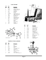
Place Blower Wheel in housing with blades
at bottom cupped towards opening.
(See illustration on other side)
B.
Install cut-off sheet.
C.
Slip Shaft through center holes of Housing
and Blower Wheel.
D.
Align Blower Wheel equidistant from each
side of Housing with equal lengths of shaft
extending beyond each side of Housing.
Tighten Blower Wheel Set Screw against
flat of Shaft with fingers.
NOTE
USE ONE DROP OF LIGHTWEIGHT OIL IN HOLE OF
EACH BEARING BEFORE INSERTING ON SHAFT.
E.
Install Bearing Insulator, Bearing Assembly,
and Plastic Thrust Washer on each end of
Shaft, as illustrated. Also install Thrust
Collar as illustrated. Tighten Set Screw of
Thrust Collar and Center Blower Wheel Set
Screw with a wrench.
F.
Slip Large Pulley on Blower Wheel Shaft
against Plastic Thrust Washer with Set
Screw outside. Tighten securely.
NOTE
SEE INSTRUCTIONS FOR ALIGNMENT
AND PROPER BELT TENSION.
INSTALLATION OF MOTOR
NOTE
CONDENSER MUST BE REMOVED BEFORE RE-
MOVING OR INSTALLING MOTOR.
A.
Install Motor Support Bar and Adjusting
Bolt on Motor before installing Motor in
Housing
B.
Place Motor in position and secure with
bolts in each end of Support Bar.
C.
Slip Small Pulley on Motor Shaft with Set
Screw out away from Motor. Have end of
Pulley flush with end of Shaft.
ALIGNMENT OF PULLEYS
NOTE
IF INSTALLATION HAS BEEN MADE
ACCORDING TO INSTRUCTIONS THE BELT ALIGN-
MENT SHOULD BE CORRECT. IF THERE SHOULD
BE ANY DOUBT, CHECK THE FOLLOWING IN-
STRUCTIONS.
A.
Place a straight edge against face of Large
Pully and align face of Small Pulley with
straight edge. Move Small Pulley for
adjustment. (Fig. 2)
B.
To put tension on belt turn Adjustment Bolt
Clockwise. (Use wrench) Hold bolt with
wrench, tighten Square Lock Nut clockwise
with a wrench.
BLOWER BELT SETTING EXTREMELY IMPORTANT
Improper belt tension and misalignment develop bearing
and belt failures.
FIGURES 1 and 2 deal with proper tension and correct
alignment of belts and pulleys when used on blower
applications.
FIGURE 1 indicates the recommended tension, deter-
mined by grasping the belt as shown and when a normal
pressure is applied, a deflection of approximately 1 in
the belt will occur.
If the deflection is much in excess of that indicated, belt
slippage may occur and excessive belt wear can result.
If the deflection is somewhat less than indicated, the belt
is too tight and will shorten the life of the bearing.
Excessive tension will actually pull the shaft through the
oil film in the bearing and allow metal to metal contact.
In addition to decreasing the bearing life, it will contrib-
ute to noisy blower operation. Any defects in the belt or
pulleys will be exaggerated.
FIGURE 2 deals with a recommended method for
checking correct alignment of pulleys. Excessive
misalignment produces increased belt wear and can
produce lateral motion of the wheel and shaft to the point
that considerable noise can develop.
Содержание FFCD
Страница 3: ...Page 3 FF FORM FINISHER LOW BASE OVERALL DIMENSIONS...
Страница 6: ...Page 6...
Страница 16: ...Page 16...
Страница 17: ...Page 17...
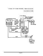
Страница 26: ...Page 26 CISSELL FF FORM FINISHER WIRING DIAGRAM 110 VOLT 60 50 CYCLE 1 PHASE 220 VOLT 60 50 CYCLE 1 PHASE...

