3-4 Cisco 7010 Hardware Installation and Maintenance
Rack-Mounting the Chassis
Step 7
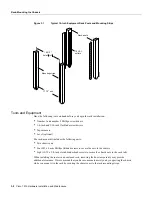
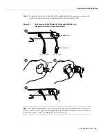
Use a number 2 Phillips screwdriver to secure two M3 x 8-mm Phillips flathead screws to
the chassis, and then repeat this procedure for the other ear. Ensure that the strip of
mounting holes on each ear is approximately flush with the end of the chassis. (See
Figure 3-2.)
Step 8
Proceed to the next section to install the chassis in the rack.
Warning
Before installing the router in a rack, and to prevent personal injury, review the section
“Safety Recommendations” in the chapter “Preparing for Installation.”
Installing the Chassis in the Rack
The ears secure the chassis to two rack posts, and the rest of the chassis is cantilevered off the ears.
After installing the ears on the chassis, mount the router by securing the ears to two posts or
mounting strips in the rack with the eight slotted screws provided. Because the ears bear the weight
of the entire chassis, be sure to use all eight slotted screws to fasten the chassis ears to the rack posts.
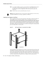
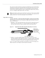
Figure 3-3 shows a typical installation in a standard, 19-inch equipment rack with four mounting
posts. Figure 3-4 shows a typical installation in a Telco-type rack, which usually has two center posts
and is bolted to the floor. If you are mounting the router in a rack with four posts, use all eight slotted
screws to mount the chassis on the front posts.
Figure 3-3
Installing the Chassis in a Four-Post, 19-Inch Rack
We recommend that you allow at least one or two inches of vertical clearance between the router and
any equipment directly above and below it. However, if necessary to save vertical space in the rack,
you can remove the four chassis feet either before or after you install the chassis in the rack. (It is
easier to grip the underside of the chassis to lift it when the feet are in place). Each rubber foot is
secured to the chassis bottom with a slotted screw. If removal is necessary, use a 3/16-inch flat-blade
screwdriver to remove the feet, then put the feet in a safe place in case you need them later.
H2057
Chassis front
Содержание TelePresence Server 7010
Страница 10: ...x Cisco 7010 Hardware Installation and Maintenence ...
Страница 14: ...iv Cisco 7010 Hardware Installation and Maintenance Document Conventions ...
Страница 112: ...2 52 Cisco 7010 Hardware Installation and Maintenance Initial Configuration Information Page ________ ...
Страница 148: ...3 36 Cisco 7010 Hardware Installation and Maintenance Using the Flash Memory Card ...
Страница 158: ...4 10 Cisco 7010 Hardware Installation and Maintenance Troubleshooting the Processor Subsystem ...
Страница 242: ...5 84 Cisco 7010 Hardware Installation and Maintenance Replacing Internal Components ...
Страница 258: ...A 16 Cisco 7010 Hardware Installation and Maintenance MIP Interface Cable Pinouts ...
Страница 270: ...B 12 Cisco 7010 Hardware Installation and Maintenance Interface Processor LEDs ...
Страница 274: ...C 4 Cisco 7000 Hardware Installation and Maintenance ...
Страница 287: ...Index 13 ...


