Preparing for Installation 2-17
Site Requirements
General Precautions
Follow these general precautions when planning your equipment locations and connections:
•
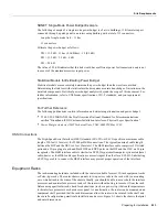
Use the show environment command regularly to check the internal system status. The
environmental monitor continuously checks the interior chassis environment; it provides
warnings for high temperature and maximum and minimum voltages, and creates reports on any
occurrences. If warning messages are displayed, such as the following, take immediate action to
identify the cause and correct the problem.
WARNING: Fan has reached CRITICAL level
OR
%ENVM-2-FAN: Fan array has failed, shutdown in 2 minutes
(Refer to the section “Environmental Monitoring and Reporting Functions” in the chapter
“Product Overview.”)
•
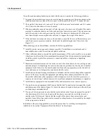
Maintain at least 2 inches of clearance on each side of the chassis to allow cooling air to flow
through the inlet and exhaust ports. Keep the sides of the chassis free from obstructions and away
from the exhaust air of other equipment. Remember that electrical equipment generates heat, and
ambient room temperature alone may not be adequate to cool equipment to acceptable operating
temperatures.
•
Do not place the router directly on the floor or in any area that tends to collect dust.
•
Follow ESD-prevention procedures to avoid damage to equipment. Damage from static discharge
can cause immediate or intermittent equipment failure.
•
Ensure that the chassis cover, backplane cover, interface processors, and any blank interface
processor fillers are in place and secure. The fans direct cooling air throughout the chassis
interior; a loose panel or empty interface processor slot can redirect the air flow away from active
components. Also, the backplane cover shields the high current present on the backplane, and the
chassis cover must be in place to maintain the EMI integrity of the system.
Equipment-Rack Ventilation
If you plan to install the router in an equipment rack, you can avoid overtemperature conditions by
following the guidelines in the section “Equipment Racks” in this chapter, in addition to the
following precautions:
•
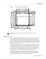
There must be at least two inches of clearance between each side of the chassis and the side (or
inner wall) of an enclosed rack. (See Figure 2-1.)
•
Enclosed racks must have adequate ventilation or an exhaust fan; use an open rack whenever
possible.
•
A ventilation system that is too powerful in a closed rack may also prevent cooling by creating
negative pressure around the chassis and redirecting the air away from the inlet vents. If
necessary, operate the chassis with the rack open.
•
The correct use of baffles in an enclosed rack can help to ensure that cool air reaches the chassis.
•
Equipment near the bottom of a rack may generate excessive heat that is drawn upward and into
the inlet ports of equipment above, leading to overtemperature conditions in devices at or near
the top of the rack.
For a functional description of the environmental monitor and the status levels, refer to the section
“Environmental Monitoring and Reporting Functions” in the chapter “Product Overview.”
Содержание TelePresence Server 7010
Страница 10: ...x Cisco 7010 Hardware Installation and Maintenence ...
Страница 14: ...iv Cisco 7010 Hardware Installation and Maintenance Document Conventions ...
Страница 112: ...2 52 Cisco 7010 Hardware Installation and Maintenance Initial Configuration Information Page ________ ...
Страница 148: ...3 36 Cisco 7010 Hardware Installation and Maintenance Using the Flash Memory Card ...
Страница 158: ...4 10 Cisco 7010 Hardware Installation and Maintenance Troubleshooting the Processor Subsystem ...
Страница 242: ...5 84 Cisco 7010 Hardware Installation and Maintenance Replacing Internal Components ...
Страница 258: ...A 16 Cisco 7010 Hardware Installation and Maintenance MIP Interface Cable Pinouts ...
Страница 270: ...B 12 Cisco 7010 Hardware Installation and Maintenance Interface Processor LEDs ...
Страница 274: ...C 4 Cisco 7000 Hardware Installation and Maintenance ...
Страница 287: ...Index 13 ...

