Maintenance 5-77
Replacing Internal Components
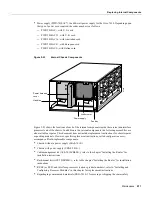
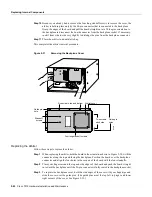
Follow these steps to remove and replace the power harness cover:
Step 1
Turn OFF the system power switch and unplug the power cord from the AC source.
Step 2
Follow Steps 1 and 2 in the section “Removing and Replacing the Chassis Cover Panel” to
open the chassis.
Step 3
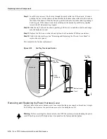
Use a number 1 Phillips screwdriver to remove the M-3 screw that secures the harness
cover to the backplane. (See Figure 5-28.)
Step 4
Holding the cover with one hand, tilt the top of the cover back toward you, then pull it
upward slightly so that the tab clears the slot in the chassis floor.
Step 5
When the tab clears the slot, pull the cover straight back off the harness and out of the
chassis.
Step 6
To replace the power harness cover, hold the cover with one hand, with the tab on the
bottom and the open side facing away from you. Tilt the top of the panel back slightly
(toward you).
Step 7
Insert the tab on the bottom of the cover into the slot in the chassis floor. (See Figure 5-27.)
Step 8
While pushing the cover downward slightly to keep the bottom tab in the slot, push the top
of the cover back over the harness wires until the sides are flush against the backplane
cover. Ensure that all of the harness wires are under the cover.
Step 9
Insert the M-3 screw through the top of the harness cover, and use a number 1 Phillips
screwdriver to tighten it.
Step 10
Follow Steps 3 through 6 in the section “Removing and Replacing the Chassis Cover Panel”
to replace the chassis cover panel.
This completes the power harness cover removal and replacement procedures.
Figure 5-27
Removing the Power Harness Cover
Power harness
cover
Arbiter cover
Power supply
Fan tray
Removing power harness cover
H1990
Содержание TelePresence Server 7010
Страница 10: ...x Cisco 7010 Hardware Installation and Maintenence ...
Страница 14: ...iv Cisco 7010 Hardware Installation and Maintenance Document Conventions ...
Страница 112: ...2 52 Cisco 7010 Hardware Installation and Maintenance Initial Configuration Information Page ________ ...
Страница 148: ...3 36 Cisco 7010 Hardware Installation and Maintenance Using the Flash Memory Card ...
Страница 158: ...4 10 Cisco 7010 Hardware Installation and Maintenance Troubleshooting the Processor Subsystem ...
Страница 242: ...5 84 Cisco 7010 Hardware Installation and Maintenance Replacing Internal Components ...
Страница 258: ...A 16 Cisco 7010 Hardware Installation and Maintenance MIP Interface Cable Pinouts ...
Страница 270: ...B 12 Cisco 7010 Hardware Installation and Maintenance Interface Processor LEDs ...
Страница 274: ...C 4 Cisco 7000 Hardware Installation and Maintenance ...
Страница 287: ...Index 13 ...

