ii Cisco 7010 Hardware Installation and Maintenance
Document Organization
Document Organization
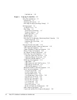
The organization of this publication follows a recommended linear installation sequence: starting
with Chapter 1, “Product Overview,” and continuing through Chapter 3, “Installing the Router.” You
will refer to Chapter 4, “Troubleshooting,” only if you experience problems with the initial hardware
installation or startup. Use the maintenance information in Chapter 5, “Maintenance,” whenever you
add, replace, upgrade, or rearrange system components.
This publication also includes some information that you may not need at initial installation, but
which can be useful when you upgrade or add components to the system. The appendices include
additional reference information. Following is a brief description of each chapter:
•
Chapter 1, “Product Overview,” describes the physical properties of the router, components, and
interfaces. It also provides brief functional descriptions of the primary system features.
•
Chapter 2, “Preparing for Installation,” is a preparatory section that describes site requirements,
safety considerations, tools required, optional and required network connection equipment,
unpacking checklists, and procedures you should perform before actual installation. This chapter
contains descriptions and illustrations of all types of network interface cables, connectors, and
interface devices that you may need for your network connections, so you can use this chapter as
a reference.
•
Chapter 3, “Installing the Router,” provides instructions for rack mounting the router, connecting
the external power and network interface cables, and starting the system. After your system
successfully initializes, you will proceed to the related software documentation to configure the
interfaces. If the system fails to initialize successfully, you will proceed to Chapter 4 to
troubleshoot the problem.
•
Chapter 4, “Troubleshooting the Installation,” provides troubleshooting guidelines for the initial
hardware installation and suggests steps to help you quickly isolate the source and resolve the
problem.
•
Chapter 5, “Maintaining the System Hardware,” provides procedures for replacing, adding,
upgrading, modifying, and rearranging system components and field-replaceable units (FRUs).
•
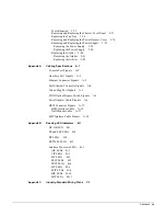
Appendix A, “Cabling Specifications,” lists pin signals for the network interface cables you will
need to connect the router interfaces to external networks.
•
Appendix B, “LED States,” describes the various states and indications of the LEDs on the power
supply, route processor (RP), switch processor (SP), and the various interface processors (IPs).
This information is of limited use at initial system startup because, although the LEDs for many
interface types go on at the initial system startup, they do not indicate an accurate status until the
interface is configured. This information is for your reference, to be used after the interfaces are
configured and brought on line.
•
Appendix C, “Industry Standard Wiring Plans,” lists the telephone industry color-code scheme
for 25-pair wires including the pin numbers.
Содержание TelePresence Server 7010
Страница 10: ...x Cisco 7010 Hardware Installation and Maintenence ...
Страница 14: ...iv Cisco 7010 Hardware Installation and Maintenance Document Conventions ...
Страница 112: ...2 52 Cisco 7010 Hardware Installation and Maintenance Initial Configuration Information Page ________ ...
Страница 148: ...3 36 Cisco 7010 Hardware Installation and Maintenance Using the Flash Memory Card ...
Страница 158: ...4 10 Cisco 7010 Hardware Installation and Maintenance Troubleshooting the Processor Subsystem ...
Страница 242: ...5 84 Cisco 7010 Hardware Installation and Maintenance Replacing Internal Components ...
Страница 258: ...A 16 Cisco 7010 Hardware Installation and Maintenance MIP Interface Cable Pinouts ...
Страница 270: ...B 12 Cisco 7010 Hardware Installation and Maintenance Interface Processor LEDs ...
Страница 274: ...C 4 Cisco 7000 Hardware Installation and Maintenance ...
Страница 287: ...Index 13 ...


