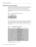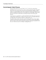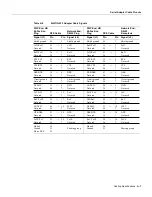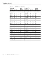
B-2 Cisco 7010 Hardware Installation and Maintenance
SP and SSP LEDs
SP and SSP LEDs
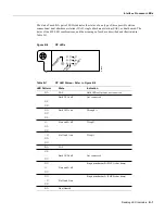
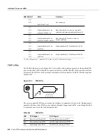
The SP and SSP have an enabled LED. The enabled LED goes on to indicate that the SP or SSP is
operational and powered up. All enabled LEDs (on the SP, SSP, and interface processors) go on
when the boot sequence is complete. If the enabled LEDs do not come on, one of the following errors
is indicated:
•
The SP or SSP or interface processor is not installed correctly (not fully seated in the backplane
connector).
•
The microcode and software that are loading at startup are not compatible.
•
The SP or SSP or interface processor has failed.
RP LEDs
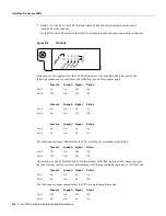
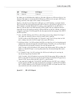
The three LEDs on the RP, which are shown in Figure B-2, indicate the system and RP status. The
normal LED goes on to indicate that the system is operational. During normal operation, the CPU
halt and boot error LEDs on the RP should be off. When the system is turned on or restarted, the boot
error LED goes on for one or two seconds, then goes off. The CPU halt LED, which goes on only if
the system detects a processor hardware failure, should stay off. If the boot error LED stays on for
more than 5 seconds, the system is unable to boot and should be restarted. A successful boot is
indicated when the boot error LED goes out; however, this does not necessarily mean that the system
has reached normal operation.
Figure B-2
RP LEDs
RSP7000 LEDs
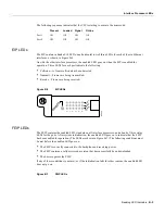
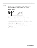
Figure B-3 shows the LEDs on the RSP7000 faceplate. The LEDs on the RSP7000 indicate the
system and RSP7000 status and which Flash memory card slot is active. The CPU halt LED, which
goes on only if the system detects a processor hardware failure, should remain off. A successful boot
is indicated when the normal LED goes on; however, this does not necessarily mean that the system
has reached normal operation. During normal operation, the CPU halt LED should be off, and the
normal LED should be on. The slot 0 and slot 1 LEDs indicate which PCMCIA (Flash memory) card
slot is in use, and each LED blinks when the card is accessed by the system.
Caution
The reset switch resets the RSP7000 and the entire system. To prevent system errors and
problems, use it only at the direction of your service representative.
Figure B-3
RSP7000 LEDs
NORMAL
BOOT ERROR
CPU HALT
H2061
Содержание TelePresence Server 7010
Страница 10: ...x Cisco 7010 Hardware Installation and Maintenence ...
Страница 14: ...iv Cisco 7010 Hardware Installation and Maintenance Document Conventions ...
Страница 112: ...2 52 Cisco 7010 Hardware Installation and Maintenance Initial Configuration Information Page ________ ...
Страница 148: ...3 36 Cisco 7010 Hardware Installation and Maintenance Using the Flash Memory Card ...
Страница 158: ...4 10 Cisco 7010 Hardware Installation and Maintenance Troubleshooting the Processor Subsystem ...
Страница 242: ...5 84 Cisco 7010 Hardware Installation and Maintenance Replacing Internal Components ...
Страница 258: ...A 16 Cisco 7010 Hardware Installation and Maintenance MIP Interface Cable Pinouts ...
Страница 270: ...B 12 Cisco 7010 Hardware Installation and Maintenance Interface Processor LEDs ...
Страница 274: ...C 4 Cisco 7000 Hardware Installation and Maintenance ...
Страница 287: ...Index 13 ...

