Product Overview 1-3
Physical Description
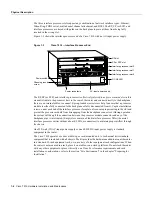
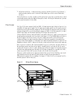
Figure 1-1
Cisco 7000 Series Routers
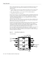
The front, or noninterface processor end, of the Cisco 7010 is a removable cover panel that is secured
with two captive slotted fasteners. (See Figure 1-2.) Removing the cover panel provides access to
the three internal components: the arbiter, power supply, and fan tray.
Figure 1-2
Cisco 7010 Chassis Cover Panel
The interface processor end of the router contains the five-processor slots, the AC-input receptacle,
the power switch, and a power status LED indicator. The processor slots contain the RP, SP (or SSP),
and up to three interface processors. When viewing the router from the interface processor end, the
RP is in the top slot (the RP slot), and the SP (or SSP) is in the slot directly below the RP. The
remaining three slots are numbered from the bottom up beginning with slot 0 (the bottom slot)
through 2 (the center slot).
H1999
I
O
DC FAIL
AC POWER
I
O
DC FAIL
AC POWER
Cisco 7000
Cisco 7010
H2952
Captive fasteners
Содержание TelePresence Server 7010
Страница 10: ...x Cisco 7010 Hardware Installation and Maintenence ...
Страница 14: ...iv Cisco 7010 Hardware Installation and Maintenance Document Conventions ...
Страница 112: ...2 52 Cisco 7010 Hardware Installation and Maintenance Initial Configuration Information Page ________ ...
Страница 148: ...3 36 Cisco 7010 Hardware Installation and Maintenance Using the Flash Memory Card ...
Страница 158: ...4 10 Cisco 7010 Hardware Installation and Maintenance Troubleshooting the Processor Subsystem ...
Страница 242: ...5 84 Cisco 7010 Hardware Installation and Maintenance Replacing Internal Components ...
Страница 258: ...A 16 Cisco 7010 Hardware Installation and Maintenance MIP Interface Cable Pinouts ...
Страница 270: ...B 12 Cisco 7010 Hardware Installation and Maintenance Interface Processor LEDs ...
Страница 274: ...C 4 Cisco 7000 Hardware Installation and Maintenance ...
Страница 287: ...Index 13 ...


