background image

 Preparing for Installation 2-13

Site Requirements

SONET Single-Mode Power Budget Example 

The following example of a single-mode power budget is of a two buildings, 11 kilometers apart, 
connected through a patch panel in an intervening building with a total of 12 connectors. 

Length of single-mode link = 11 km

12 connectors

Estimate the power budget as follows:

PB = 11.5 dB – 11 km (0.5 dB/km) – 12 (0.5 dB) 

PB = 11.5 dB – 5.5 dB – 6 dB

PB = 2.5 dB

The value of 2.5 dB indicates that this link would have sufficient power for transmission and is not 
in excess of the maximum receiver input power.

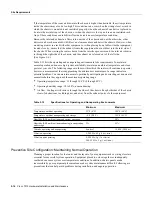
Statistical Models for Estimating Power Budget 

Statistical models more accurately determine the power budget than the worst case method. 
Determining the link loss with statistical methods requires accurate knowledge of variations in the 
data link components. Statistical power budget analysis is beyond the scope of this document. For 
further information, refer to UNI Forum specifications, ITU-T standards, and your equipment 
specifications.

For Further Reference

The following publications contain information on determining attenuation and power budget:

T1E1.2/92-020R2 ANSI, the Draft American National Standard for Telecommunications 
entitled “Broadband ISDN Customer Installation Interfaces: Physical Layer Specification.”

Power Margin Analysis, AT&T Technical Note, TN89-004LWP, May 1989.

HSSI Connections

The High-Speed Serial Interface (HSSI) standard (EIA/TIA-612/613) specifies a maximum cable 
length of 50 feet (15 meters) for 52 Mbps HSSI connections. The typical (nominal) cable length 
between the HIP and the DSU is 6 feet (2 meters). The HSSI interface cable comprises 25 twisted 
pairs and a 50-pin plug at each end. Both DTE and DCE ports on the HIP and the DSU are 50-pin 
receptacles. The HSSI interface cable is similar to a SCSI-II-type (small computer systems interface) 
cable; however, the HSSI cable specification is more stringent than that for a SCSI-II. Substituting 
a SCSI-type cable to connect the HSSI interface may prevent proper operation of the interface.

Equipment Racks 

The rack-mounting hardware included with the router is suitable for most 19-inch equipment racks 
or Telco-type racks. The router chassis mounts to two posts or rails in the rack with two mounting 
ears, which attach to the sides of the chassis. Ideally, you should be able to access both the interface 
processor and noninterface processor ends of the router without having to remove it from the rack. 
Before using a particular rack, check for obstructions (such as a power strip) that could impair access 
to the interface processors or chassis cover panel. As an alternative, the router can be mounted on an 
equipment shelf, provided that the rack dimensions allow the router to be secured to the shelf and 
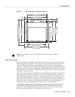
the overall configuration permits safe installation and access. Figure 2-1 shows the chassis footprint 
and outer dimensions.

Содержание TelePresence Server 7010

Страница 1: ...rporate Headquarters 170 W Tasman Drive San Jose CA 95134 1706 USA 408 526 4000 800 553 NETS Cisco 7010 Hardware Installation and Maintenance Customer Order Number DOC 7010IM2 Text Part Number 78 1222 05 ...

Страница 2: ...Inc Mountain View California NCD makes no representations about the suitability of this software for any purpose The X Window System is a trademark of the Massachusetts Institute of Technology Copyright 1987 Digital Equipment Corporation Maynard Massachusetts and the Massachusetts Institute of Technology Cambridge Massachusetts All rights reserved THIS MANUAL AND THE SOFTWARE OF THE ABOVE LISTED S...

Страница 3: ...iation calculated on a straight line basis Customer agrees to cooperate with Cisco or its Sales or Service Partner in creating the environment in which the error occurred Further Customer agrees to supply any necessary equipment for such tests This Limited Warranty does not apply to Software which 1 has been altered except as authorized by Cisco 2 has not been installed operated repaired or mainta...

Страница 4: ... at Cisco s option and through a Sales or Service Partner if necessary to either i provide advance replacement service as described above ii replace the Product with a Product that does not contain the defect or iii refund the price paid for the Hardware less depreciation calculated on a straight line basis Exclusions The above warranty does not apply to any Product which 1 has been altered except...

Страница 5: ...00CI 1 19 Switch Processor SP 1 20 Silicon Switch Processor SSP 1 21 Interface Processors 1 21 ATM Interface Processor AIP 1 22 Channel Interface Processor CIP 1 24 Ethernet Interface Processor EIP 1 25 Fast Ethernet Interface Processor 1 25 Fiber Distributed Data Interface Processor FIP 1 26 Fast Serial Interface Processor FSIP 1 28 HSSI Interface Processor HIP 1 32 MultiChannel Interface Process...

Страница 6: ...chment Connection Equipment 2 23 Ethernet Connection Equipment 2 23 Fast Ethernet Connection Equipment 2 27 Token Ring Connection Equipment 2 28 Token Ring Cables and Connectors 2 29 Token Ring Physical Connections 2 29 Token Ring Fault Management 2 31 FDDI Connection Equipment 2 32 FDDI Media 2 32 FDDI Transceivers and Cable Connectors 2 33 FDDI Physical Connections 2 33 FDDI Fault Management 2 3...

Страница 7: ...thernet Connections 3 14 Channel Attachment Connections 3 15 Token Ring Connections 3 15 FDDI Connections 3 16 Single Attach Connections 3 17 Dual Attach Connections 3 18 Installing an Optical Bypass Switch 3 20 Serial Connections 3 22 Connecting DTE and DCE Devices 3 22 Connecting to Metric Based Devices 3 23 HSSI Connections 3 24 MultiChannel Connections 3 25 Connecting the Console Terminal 3 25...

Страница 8: ... Replacing the ROM 5 10 Verifying the Microcode Version 5 11 RP and RSP7000 Configurations 5 13 Configuring Jumpers 5 13 Software Configuration Register 5 17 Saving and Retrieving the Configuration File 5 24 Copying the Configuration File 5 26 Retrieving the Configuration File 5 28 Copying Files Between NVRAM and a Flash Memory Card 5 29 Replacing System Software EPROMs 5 30 Replacing RP SIMMs Upg...

Страница 9: ...als A 2 Auxiliary Port Signals A 2 Ethernet Connector Signals A 3 Fast Ethernet Connector Signals A 4 Token Ring Port Signals A 5 FDDI Optical Bypass Switch Signals A 5 Serial Adapter Cable Pinouts A 6 HSSI Connector Signals A 12 HSSI Interface Cable A 12 Null Modem Cable A 13 MIP Interface Cable Pinouts A 14 Appendix B Reading LED Indicators B 1 DC OK LED B 1 SP and SSP LEDs B 2 RP LEDs B 2 RSP70...

Страница 10: ...x Cisco 7010 Hardware Installation and Maintenence ...

Страница 11: ...uct information All Cisco technical documentation and selected marketing materials are available on UniverCD Cisco s online library of product information UniverCD us updated and shipped monthly so it may be more up to date than printed documentation UniverCD is available both as a single CD and as an annual subscription To order UniverCD contact your local sales representative or call Customer Se...

Страница 12: ...nections so you can use this chapter as a reference Chapter 3 Installing the Router provides instructions for rack mounting the router connecting the external power and network interface cables and starting the system After your system successfully initializes you will proceed to the related software documentation to configure the interfaces If the system fails to initialize successfully you will ...

Страница 13: ...mands and keywords are in boldface font Arguments for which you supply values are in italic font Elements in square brackets are optional Alternative but required keywords are grouped in braces and separated by vertical bars Examples use these conventions Terminal sessions and sample console screen displays are in screen font Information you enter is in boldface screen font Nonprinting characters ...

Страница 14: ...iv Cisco 7010 Hardware Installation and Maintenance Document Conventions ...

Страница 15: ...ocode upgrades allows you to load new images into Flash memory remotely without having to physically access the router for fast reliable upgrades This chapter provides physical and functional overviews to familiarize you with your new router It contains physical descriptions of the system hardware and major components and functional descriptions of hardware related features Descriptions and exampl...

Страница 16: ...The Cisco 7000 provides five interface slots and offers a second modular power supply for redundant power The Cisco 7010 provides three interface slots and the same performance as the Cisco 7000 at a lower cost Table 1 1 shows a comparison of the two Cisco 7000 series products Figure 1 1 shows the interface processor end of both models Table 1 1 Comparison of Cisco 7000 Series Routers Feature Cisc...

Страница 17: ...rface processor end of the router contains the five processor slots the AC input receptacle the power switch and a power status LED indicator The processor slots contain the RP SP or SSP and up to three interface processors When viewing the router from the interface processor end the RP is in the top slot the RP slot and the SP or SSP is in the slot directly below the RP The remaining three slots ...

Страница 18: ...sengaging from the backplane connectors During operation the system will hang if the connection between the processor module connector and any of the backplane pins is interrupted Empty slots contain a blank interface processor filler the metal interface processor carrier without a board LEDs or connectors to maintain proper airflow through the chassis One 550 watt W AC input power supply or one 6...

Страница 19: ...voltage 100 to 240 VAC wide input with power factor corrector PFC Power distribution 70A maximum 5 VDC 15A maximum 12 VDC 3A maximum 12 VDC 5A maximum 24 VDC Frequency 50 to 60 Hz AC current rating 9A maximum at 100 VAC 4A maximum at 240 VAC at 600W DC input voltage 40 volts DC VDC minimum in North America 56 VDC in Europe 48 VDC nominal in North America 60 VDC in Europe 52 VDC maximum in North Am...

Страница 20: ...nts in their normal operating positions Figure 1 4 Internal Components at Noninterface Processor End of Router Arbiter The arbiter which arbitrates traffic on the CxBus and generates the CxBus clock is a printed circuit board that is mounted to the front noninterface processor side of the backplane See Figure 1 4 The arbiter arbitrates traffic across the CxBus by prioritizing access requests from ...

Страница 21: ...ps head screws secure the power supply to the chassis interior The power supply delivers DC power to the internal components through a wiring harness that plugs into a polarized receptacle to the noninterface processor side of the backplane An aluminum cover shields the harness and power connection The backplane distributes the DC voltages to the fan tray arbiter and interface processor bus connec...

Страница 22: ...ly two small fans draw cooling air through the power supply interior The air flows in one side of the supply and out the other side following the same direction as the chassis cooling air See Figure 1 6 In addition to the environmental monitoring performed by the system software the power supply monitors its own temperature and internal voltages If the supply detects an overvoltage or overtemperat...

Страница 23: ...If the temperature inside the chassis exceeds the normal range the fan control board increases the fan speed to provide additional cooling air to the internal components If the temperature continues to rise the fan control board linearly increases the fan speed until the fans reach full speed 100 percent If the internal temperature exceeds the specified threshold the system environmental monitor s...

Страница 24: ...interface processor in any interface processor slot Caution When installing an RP SP SSP or interface processor ensure that you are installing it in the appropriate slot to avoid damaging the key guides or the backplane Figure 1 8 Backplane Slot Keys RP SP or SSP CxBus FIP Single port FDDI interface processor 68040 CPU Flash EPROM 16 MB DRAM ENVM Logic CxBus FSIP 4 8 port fast serial interface pro...

Страница 25: ...m Sending and receiving routing protocol updates Managing tables and caches Monitoring interface and environmental status Providing SNMP management and the console Telnet interface The RP must be installed in the top processor slot which is labeled RP Memory Components Table 1 3 lists the functions of the various types of memory on the RP and Figure 1 9 shows the locations of each Table 1 3 RP Mem...

Страница 26: ...fault system software EPROMs If replacement is necessary in the future refer to the section RP and RSP7000 Configurations in the chapter Maintenance and to the replacement instructions that accompany the upgrade kit DRAM Dynamic random access memory DRAM stores routing tables protocols and network accounting applications The DRAM resides on four single in line memory modules SIMMs The standard RP ...

Страница 27: ...Bootstrap Version 4 7 2 1 or a later 4 7 version RP board revision B0 or later If your system contains Cisco Internetwork Operating System Cisco IOS Release 10 0 the minimum requirements are as follows Release 10 0 1 or a later 10 0 image in ROM System Bootstrap Version 5 0 1 or a later 5 0 bootstrap version RP board revision B0 or later Bootstrap Version 4 6 is used exclusively with Software Rele...

Страница 28: ...l have to reenter it manually This procedure is not necessary if you are temporarily removing an RP you will reinstall lithium batteries retain the configuration in memory until you replace the RP in the system Flash Memory The Cisco 7010 contains two types of Flash memory onboard imbedded and on a Flash memory card that can be optionally installed in a slot on the RP The Flash memory card is requ...

Страница 29: ...m software EPROMs You need to reset these jumpers only if you upgrade the system software by replacing the ROMs instead of downloading the new image and if the size capacity of the new EPROMs is greater than those you replace For a detailed description of all jumper functions and settings refer to the section RP and RSP7000 Configurations in the chapter Maintenance LEDs The three LEDs on the RP in...

Страница 30: ... 10 3 9 or later For the RSP7000 to operate properly the Cisco 7010 chassis must also be configured with the 7000 Series Chassis Interface RSP7000CI which installs in the 7000 CI slot slot 4 in the Cisco 7010 The Cisco IOS images reside in Flash memory which is located either on the RSP7000 in the form of a single in line memory module SIMM or on up to two Personal Computer Memory Card Internation...

Страница 31: ...ons of each type Figure 1 10 7000 Route Switch Processor RSP7000 Table 1 4 RSP7000 Memory Components Type Size Quantity Description Location DRAM 16 to 128 MB 2 to 4 8 16 or 32 MB SIMMs based on maximum DRAM required Bank 0 U4 and U12 Bank 1 U18 and U25 NVRAM 128 KB 1 Nonvolatile EPROM for the system configuration file1 1 A system configuration file is contained in NVRAM which allows the software ...

Страница 32: ...reinstall lithium batteries retain the configuration in memory until you replace the RSP7000 in the system Flash Memory The imbedded or PCMCIA card based Flash memory allows you to remotely load and store multiple Cisco IOS and microcode images You can download a new image over the network or from a local server and then add the new image to Flash or replace the existing files You can then boot ro...

Страница 33: ...tries Association Telecommunications Industry Association EIA TIA 232 receptacle female that provides a data circuit terminating equipment DCE interface for connecting a console terminal Note EIA TIA 232 was known as recommended standard RS 232 before its acceptance as a standard by the Electronic Industries Association EIA and Telecommunications Industry Association TIA The auxiliary port is an E...

Страница 34: ...n control Figure 1 11 RSP7000CI Switch Processor SP The SP shown in Figure 1 12 controls and communicates with the interface processors on the high speed CxBus Its function is to decide the destination of a packet and switch it based on that decision The SP uses a 16 million instructions per second mips processor to provide high speed autonomous switching and routing The SP microcode firmware whic...

Страница 35: ...stall and remove them without opening the chassis and without turning off the chassis power The early serial interface processor known as the SX SIP or PRE FSIP will not operate in the Cisco 7010 see the following Caution The RP SP and SSP which are required system components always reside in the RP SP and SSP slots See Figure 1 3 The remaining three slots are available for any combination of the ...

Страница 36: ... contain upgraded microcode images which will load automatically when the new software image is loaded Although most upgrades support the downloadable microcode feature and are distributed on floppy disk some may require ROM replacement If replacement is necessary refer to the section Microcode Component Replacement in the chapter Maintenance Also specific instructions are provided with the replac...

Страница 37: ...sembly of up to 512 buffers simultaneously Each buffer represents a packet Support for up to 2 048 virtual circuits Support for both ATM Adaptation Layer AAL 5 and AAL3 4 Note AAL3 4 is not supported in the initial release of Cisco IOS Release 10 0 AAL3 4 is supported with Cisco IOS Release 10 2 and later Exception queue which is used for event reporting Events such as CRC errors are reported to t...

Страница 38: ...tput architectures for the CIP include ESA 390 for ESCON and System 370 370 Xa and ESA 390 for bus and tag The ESCON interface is capable of a data rate up to 17 megabytes per second MBps and the bus and tag interface is capable of a data rate up to 4 5 MBps Figure 1 14 Channel Interface Processor CIP Following are the functions of the CIP LEDs Enabled Indicates that the CIP has been enabled for o...

Страница 39: ... attachment unit MAU and attachment unit interface AUI cable to connect to the external network For descriptions of Ethernet transceivers and AUIs refer to the section Ethernet Connection Equipment in the chapter Preparing for Installation For descriptions of Ethernet network connections refer to the section Ethernet Connections in the chapter Installing the Router Each port on the EIP automatical...

Страница 40: ...aximum port densities refer to the section Port Densities in this chapter Fiber Distributed Data Interface Processor FIP The FIP contains a 16 mips processor for high speed 100 Mbps interface rates and the industry standard AMD SuperNet chipset for interoperability Figure 1 17 shows a multimode multimode FIP on the bottom and a single mode multimode FIP on the top The FIP supports single attach st...

Страница 41: ...h station SAS or dual attach station DAS For complete descriptions of the LED states refer to the appendix Reading LED Indicators Each FIP provides the interface for connection to a Class A DAS with primary and secondary rings or to a Class B SAS with only a primary ring The Cisco 7010 supports up to three FIPs for a maximum of 3 FDDI network connections The multimode MIC or single mode FC ports o...

Страница 42: ...one that fails however you cannot upgrade a four port FSIP to an eight port by adding port adapters The 4 port FSIP is not constructed to support additional ports after it leaves the factory it contains the circuitry to control only one 4 port module For port adapter descriptions refer to the section Universal Serial Port Adapters in this chapter The default FSIP microcode resides on a PLCC type R...

Страница 43: ...ration instructions refer to the related software documentation which is available on UniverCD Figure 1 18 shows the FSIP LEDs As with the other interface processors the enabled LED is on when the FSIP is enabled for operation The four LEDs below each port indicate the state of that interface The labels on each LED indicate the signal state when the FSIP port is in DTE mode However the direction o...

Страница 44: ... 25 for EIA TIA 232 and EIA 530 DB 37 for EIA TIA 449 DB 15 for X 21 or a standard V 35 block connector For most interface types the adapter cable for DTE mode uses a plug at the network end and the cable for DCE mode uses a receptacle at the network end However V 35 adapter cables are available with either a V 35 plug or a receptacle for either mode and EIA 530 is available only in DTE mode with ...

Страница 45: ...nfigured at the factory with from one to four E1 G 703 G 704 port adapters Each port adapter provides two 15 pin D shell DB 15 receptacles which support only E1 G 703 G 704 interfaces The FSIP E1 G 703 G 704 interface uses a DB 15 receptacle for both the balanced and unbalanced ports The label adjacent to the port indicates whether the port is balanced or unbalanced you must connect the correct ty...

Страница 46: ...receive clock signal During normal operation this signal is received from the external DSU During loopback this signal is generated internally RD Receive Data On when the HIP detects packet traffic and indicates that the HIP is able to receive packets from the external DSU ST Send Timing On when the HIP is sending a transmit clock signal to the external DSU During normal operation this signal is d...

Страница 47: ... The MIP provides up to two channelized E1 or T1 connections via serial cables to a channel service unit CSU On the MIP two controllers can each provide up to 24 virtual channels Each virtual channel is presented to the system as a serial interface that can be configured individually The MIP shown in Figure 1 22 provides two controllers for transmitting and receiving data bidirectionally at the T1...

Страница 48: ... the LED states refer to the appendix Reading LED Indicators The TRIP is available with two or four ports The Cisco 7010 supports up to 3 TRIPs for a maximum of 12 Token Ring ports Each port requires a media access unit MAU to connect the DB 9 TRIP connectors to the external Token Ring networks For descriptions of Token Ring connectors and MAUs refer to the section Token Ring Connection Equipment ...

Страница 49: ...stem software also assigns a logical interface address to each interface which is included in some of the status displays The logical address is used in our other modular platforms A type M and C chassis and is present in all router software but it is not implemented or needed in the Cisco 7000 series routers A third type of address is the MAC layer or hardware address which is a standardized data...

Страница 50: ...aces on an eight port FSIP are numbered 0 through 7 and so on You can identify interface ports by physically checking the slot port location on the back of the router or by using software commands to display information about a specific interface or all interfaces in the router To display information about every interface use the show interfaces command interfaces is plural without variables To di...

Страница 51: ...ferent method of handling the MAC addresses in Cisco 7000 series routers OIR allows you to remove an interface processor and replace it with another identically configured one If the new interfaces match the current configuration that of the interfaces you removed the system immediately brings them on line In order to allow OIR an address allocator with 40 unique MAC addresses is stored in an EEPR...

Страница 52: ...h RP SP or SSP and interface processor contains a bus connector with which it connects to the system backplane The bus connector is a set of tiered pins in three lengths The pins send specific signals to the system as they make contact with the backplane The system assesses the signals it receives and the order in which it receives them to determine what event is occurring and what task it needs t...

Страница 53: ... of a software maintenance release microcode upgrades are no longer distributed individually The default operation is to load the microcode from the bundled image At system startup an internal system utility scans for compatibility problems between the installed interface processor types and the bundled microcode images then decompresses the images into running memory RAM The bundled microcode ima...

Страница 54: ...ributed on floppy disk some exceptions may require ROM replacement If so refer to the chapter Maintenance for replacement procedures Instructions are also provided with the upgrade kit For complete command descriptions and instructions refer to the related software documentation Environmental Monitoring and Reporting Functions The environmental monitoring and reporting functions enable you to main...

Страница 55: ...em will display a warning message and shut down in two minutes Immediate operator action is required Processor shutdown The processor has detected a temperature or fan failure condition that could result in physical damage to system components and has disabled all DC power Immediate operator action is required Before shutdown the system logs the status of monitored parameters in NVRAM so that you ...

Страница 56: ...n it logs the event as an intermittent powerfail The reporting functions display the cumulative number of intermittent powerfails logged since the last power up Environmental Reports The system displays warning messages on the console if processor monitored parameters exceed a desired threshold or if a fan failure occurs You can also retrieve and display environmental status reports with the show ...

Страница 57: ...command retrieves and displays the NVRAM log of the reason for the last shutdown and the environmental status at that time If no status is available it displays the reason as unknown 7010 show env last Environmental Statistics Environmental status as of Sat 10 31 1992 16 42 48 Data is 10 second s old refresh in 50 second s All Environmental Measurements are within specifications LAST Environmental...

Страница 58: ...8 If so even if the Airflow temperature is shown within the Warning range ignore the message This is an anomaly and it will not affect operation The thresholds were corrected in Software Releases 9 17 8 and 9 21 2 In the following example all current measured values fall within the Normal status range The first voltage parameter in the table 12 V shows that the Normal range for the 12V sense spans...

Страница 59: ...econd s old refresh in 29 second s WARNING Fan has reached CRITICAL level Power Supply 550W AC No Intermittent Powerfails 12 volts measured at 12 00 V 5 volts measured at 5 02 V 12 volts measured at 12 05 V 24 volts measured at 23 70 V Airflow temperature measured at 35 C Inlet temperature measured at 26 C Fan Shutdown When the system power is on all six fans in the fan array must be operational I...

Страница 60: ...he system will display the following message on the console screen and in the show environment display when the system restarts Queued messages ENVM 1 SHUTDOWN Environmental Monitor initiated shutdown For complete command descriptions and instructions refer to the related software configuration and command reference documentation ...

Страница 61: ...ironment Equipment rack installation considerations Preventive site configuration Network connections optional and additional equipment such as connectors cables and media interface devices that you will need for connections to your Ethernet Token Ring FDDI serial or HSSI networks Tools required for installation Initial configuration information that you will need Installation Checklist a table th...

Страница 62: ...id lifting the chassis by yourself Ensure that your footing is solid and balance the weight of the object between your feet Lift the chassis slowly never move suddenly or twist your body as you lift Keep your back straight and lift with your legs not your back If you must bend down to lift the chassis bend at the knees not at the waist to reduce the strain on your lower back muscles Lift the chass...

Страница 63: ...o protect the module use an antistatic strap whenever handling processor modules Handle the carriers by the handles and the carrier edges only never touch the boards or connector pins Caution Always tighten the captive installation screws on RP SP or SSP and interface processors See Figure 5 1 These screws prevent accidental removal provide proper grounding for the system and help to ensure that t...

Страница 64: ...uration and prepare your site before installation After installation make sure the site maintains an ambient temperature of 32 F through 104 F 0 C through 40 C and keep the area around the chassis as free from dust as is practical The following sections address the site environment requirements for the router AC and DC Power The 550W wide input AC input power supply uses a power factor corrector P...

Страница 65: ...e the infrequent but potentially catastrophic problems just described without pulse meters and other special equipment These problems can cost a great deal of time to identify and resolve so take precautions by providing a properly grounded and shielded environment with special attention to issues of electrical surge suppression The ground screw on the left side of the interface processor end of t...

Страница 66: ...r and 100BaseT4 which is 100BaseT using Category 3 4 or 5 UTP or shielded twisted pair STP cabling with four pairs 100BaseT4 is also called 4T or T2 which is 2 pair UTP over Category 3 cable Table 2 2 lists the cabling specifications for 100 Mbps transmission over 100BaseT Category 5 UTP and MII connections Table 2 2 Connection Limits for 100 Mbps Transmission Table 2 3 summarizes the characterist...

Страница 67: ...tachment Connections Referring to the CIP the maximum transmission distance for ESCON with LED is 1 9 miles 3 1 km point to point or 5 7 miles 9 2 km with two ESCON Directors The maximum transmission distance for bus and tag is 400 feet 122 m The IBM 3044 C D host side remote side copper to fiber repeater can be used to extend the bus and tag distance up to 1 2 miles 2 km E1 G 703 G 704 Connection...

Страница 68: ...d sets the maximum distances between stations to the fiber lengths shown in Table 2 5 The maximum circumference of the FDDI network is only half the specified distance because of signal wrapping or loopback during fault correction The standard allows a maximum of 500 stations Both single mode and multimode transceiver types provide 11 dB of optical power Table 2 5 FDDI Maximum Transmission Distanc...

Страница 69: ... optic transmission defines two types of fiber single mode and multimode Modes can be thought of as bundles of light rays entering the fiber at a particular angle Single mode fiber allows only one mode of light to propagate through the fiber while multimode fiber allows multiple modes of light to propagate through the fiber As multiple modes of light propagate through the fiber they travel differe...

Страница 70: ...rsion spreading of the signal in time because of the different propagation modes in the fiber Attenuation is significantly lower for optical fiber than for other media For multimode transmission chromatic and modal dispersion reduce the available power of the system by the combined dispersion penalty in decibels dB The power lost over the data link is the sum of the component dispersion and modal ...

Страница 71: ... is positive as a rule the link will work Table 2 10 lists the factors that contribute to link loss and the estimate of the link loss value attributable to those factors Table 2 10 Estimating Link Loss After calculating the power budget minus the data link loss the result should be greater than zero Results less than zero may have insufficient power to operate the receiver For SONET versions of th...

Страница 72: ...dB PB 1 5 dB The value of 1 5 dB indicates that this link would have sufficient power for transmission However due to the dispersion limit on the link 4 km x 155 52 MHz 500 MHzkm this link would not work with multimode fiber In this case single mode fiber would be the better choice Single Mode Transmission The single mode signal source is an injection laser diode Single mode transmission is useful...

Страница 73: ...te TN89 004LWP May 1989 HSSI Connections The High Speed Serial Interface HSSI standard EIA TIA 612 613 specifies a maximum cable length of 50 feet 15 meters for 52 Mbps HSSI connections The typical nominal cable length between the HIP and the DSU is 6 feet 2 meters The HSSI interface cable comprises 25 twisted pairs and a 50 pin plug at each end Both DTE and DCE ports on the HIP and the DSU are 50...

Страница 74: ...ng or moving interface processors connecting cables or replacing or upgrading components Maintain a minimum clearance of two inches on each side of the chassis for the cooling air inlet and exhaust ports Avoid placing the router in an overly congested rack or directly next to another equipment rack Otherwise the heated exhaust air from other equipment can enter the inlet air vents and cause an ove...

Страница 75: ...um of two inches of clearance on both the inlet and exhaust sides of the chassis If the airflow is blocked or restricted or if the inlet air is too warm an overtemperature condition can occur Under extreme conditions the environmental monitor will shut down the power to protect the system components To help maintain normal operation and avoid unnecessary maintenance plan your site configuration an...

Страница 76: ...hose within which the router will continue to operate however a measurement that is approaching the minimum or maximum of a range indicates a potential problem You can maintain normal operation by anticipating and correcting environmental anomalies before they approach the maximum operating range Operating temperature range 32 through 104 F 0 through 40 C Operating humidity range 10 to 90 nonconde...

Страница 77: ...e cover interface processors and any blank interface processor fillers are in place and secure The fans direct cooling air throughout the chassis interior a loose panel or empty interface processor slot can redirect the air flow away from active components Also the backplane cover shields the high current present on the backplane and the chassis cover must be in place to maintain the EMI integrity...

Страница 78: ...on and configuration procedures are complete Note The console and auxiliary serial ports are asynchronous and the FSIP serial ports are synchronous When connecting serial devices such as modems or DSUs connect only asynchronous devices to the console and auxiliary ports and synchronous devices to the FSIP serial ports To use an IEEE 802 3 or Ethernet interface thick wire thin wire or unshielded tw...

Страница 79: ...E3 is the European equivalent of T3 that operates at 34 Mbps SONET Synchronous Optical NETwork is an international standard ANSI CCITT for standardizing the use of optical communications systems STS 1 Synchronous Transport Signal level 1 is the basic building block signal of SONET level 1 is 51 84 Mbps Faster SONET rates are defined as STS n where n is a multiple of 51 84 Mbps For example the rate...

Страница 80: ...nterfaces Refer to the ATM UNI specification for additional details ATM UNI information is arranged into a MIB fashion MIB attributes are readable and writable across the Interim Local Management Interface ILMI using a Simple Network Management Protocol SNMP The ILMI uses SNMP without UDP and interface processor addressing along with the ATM MIB The AIP supports RFC 1213 interface MIBs as specifie...

Страница 81: ...pertures This product meets the Class 1 Laser Emission Requirement from CDRH FDDI For E3 and DS3 connections use the 75 ohm RG 59 coaxial cable CAB ATM DS3 E3 which has bayonet style twist lock BNC connectors and ferrite beads See Figure 2 6 The E3 and DS3 PLIMs both require cable CAB ATM DS3 E3 Figure 2 6 CAB ATM DS3 E3 Cable RG 59 Coaxial Cable with BNC Connectors Caution To ensure compliance wi...

Страница 82: ...2 7 MIC Connector on a 4B 5B PLIM For multimode SONET connections connect the multimode cable to the SC connector on the PLIM See Figure 2 8 Figure 2 8 SONET Multimode SC Duplex PLIM The SONET multimode SC duplex connector is shipped with a dust plug See Figure 2 9 Remove the plug by pulling on the plug as you squeeze the sides Figure 2 9 SONET ATM Multimode Fiber Optic Transceiver and Dust Plug H...

Страница 83: ...receive port RCVR Channel Attachment Connection Equipment The ESCON Channel Adapter ECA and bus and tag Parallel Channel Adapter PCA for the CIP are available as FRUs however they are field replacable by Cisco certified field service personnel only For more information on the ECA PCA and CIP refer to the configuration note Channel Interface Processor CIP Installation and Configuration Document Num...

Страница 84: ...ons are damaged and the stations must retransmit them The stations detect the collision and use backoff algorithms to determine when they should retransmit Both Ethernet and IEEE 802 3 are broadcast networks which means that all stations see all transmissions Each station must examine received frames to determine whether it is the intended destination and if it is pass the frame to a higher protoc...

Страница 85: ...nsceiver and it is connected to the station with a transceiver cable The IEEE 802 3 specification refers to the same type of device as a media attachment unit MAU and to the cable as an attachment unit interface AUI Both transceiver cables and AUIs can connect to the EIP ports directly Transceivers are available from a variety of sources for thick wire 10Base5 thin wire 10Base2 or unshielded twist...

Страница 86: ...ons on other interface processors Typically Ethernet connectors have either slide type or jackscrew type locks See Figure 2 14 The most common are those that use a slide type lock which is the type used on the EIP ports The connector on the left in Figure 2 14 shows a slide type lock When the cable is connected to the BNC connectors to thin wire or thick wire Ethernet network Ethernet XCVR 15 pin ...

Страница 87: ... single MII 40 pin D shell type and a single RJ 45 You can use either one or the other Only one connector can be used at one time The FEIP can have up to two port adapters installed Each connection supports IEEE 802 3u interfaces compliant with the 100BaseX and 100BaseT standards The RJ 45 connection does not require an external transceiver however the MII connection does depending on the type of ...

Страница 88: ...each TRIP port and the MAU or MSAU Lobe cables connect each Token Ring station TRIP port to the MAU or MSAU and patch cables can connect adjacent MSAUs to form one large ring TRIP ports operate at either 4 or 16 Mbps The default speed for all TRIP ports is 4 Mbps which you can change to 16 Mbps on any port with the configuration command ring speed n where n is the speed 4 or 16 in Mbps The speed o...

Страница 89: ...ng refers to both IBM s Token Ring Network which IBM developed in the 1970s and to IEEE 802 5 networks The IEEE 802 5 specification was modeled after and still closely shadows IBM s network The two types are compatible although the specifications differ slightly The IBM Token Ring specifies a star topology with all end stations connected through a device called a multistation access unit MSAU IEEE...

Страница 90: ...have information to transmit seizes the token alters a bit of the token frame which changes the free token to a busy token appends the information it wishes to transmit and then sends this information to the next station on the ring The busy token with the information frame circulates the ring until it reaches the intended destination station which copies the information for further processing and...

Страница 91: ...rity stations are finished transmitting then reinstate the previous lower priority When the station detects a free token with the higher priority it assumes that there is no more higher priority traffic waiting and downgrades the priority of the token before passing it back onto the ring Early token release allows a station to release a new token onto the ring immediately after transmitting instea...

Страница 92: ...e section Token Ring Connections in the chapter Installing the Router For complete descriptions and examples of software commands refer to the related software configuration and command reference documentation which is available on UniverCD FDDI Connection Equipment Fiber optic transceivers on the FIP provide a direct interface between the router and the FDDI ring The FIP supports both single mode...

Страница 93: ...e cables for connection to the multimode MIC connectors on the FIP however not all manufacturers use the same type of DIN connector for the control port Some manufacturers use a DIN and some use a smaller version a mini DIN The optical bypass control port on the FIP requires a mini DIN connector A DIN to mini DIN adapter cable CAB FMDD is included with the multimode multimode FIP to ensure that yo...

Страница 94: ...ult tolerance If a station on a dual ring shuts down or fails such as Station 3 in Figure 2 23 the ring automatically wraps doubles back on itself to form a single contiguous ring This removes the failed station from the ring but allows the other stations to continue operation In Figure 2 23 the ring wraps to eliminate Station 3 and forms a smaller ring that includes only Stations 1 2 and 4 Note E...

Страница 95: ... to wrap back on itself Figure 2 24 shows an optical bypass switch installed at Station 1 In the normal configuration shown on the left Station 1 is functioning normally so the optical bypass switch appears transparent The switch essentially allows the signals to pass through it without interruption However if Station 1 fails the optical bypass switch enables the bypassed configuration shown on th...

Страница 96: ...stains the ring MultiChannel MIP Connection Equipment The MIP T1 interface cable has two 15 pin DB connectors at each end to connect the MIP with the external CSU Figure 2 25 shows the MIP interface cable connectors and pin outs Figure 2 25 MIP Interface Cable Connector Station 4 Station 3 Station 2 Station 1 B A B A B A Optical bypass switch Normal configuration A B Station 4 Station 3 Station 2 ...

Страница 97: ...onnections with DB 15 Connectors Figure 2 28 E1 Interface Cable for 120 Ohm Balanced Connections with Twinax Connectors Figure 2 29 E1 Interface Cable for 120 Ohm Balanced Connections with RJ 45 Connector Serial Connection Equipment The FSIP supports synchronous serial connections at T1 and E1 speeds the actual speed depends on the type of electrical interface used the distances the signals must t...

Страница 98: ...ept EIA 530 are available in DTE mode with a plug at the network end or in DCE mode with a receptacle at the network end The mode DCE or DTE is labeled on the connectors at both ends of the cables Figure 2 30 Serial Port Adapter Cables Metric M3 thumbscrews are included with each port adapter cable to allow connection to devices that use metric hardware Following are the available interface cable ...

Страница 99: ...hm Balanced Connections with Twinax Connectors and Cables Caution It is a requirement of the statutory approval of the E1 G 703 G 704 interface that the jackscrews on the DB 15 connector backshell are securely screwed down while the FSIP is operating NRZ and NRZI Formats All data communications interfaces support both nonreturn to zero NRZ and nonreturn to zero inverted NRZI formats Both formats u...

Страница 100: ... area networks WANs IEEE 802 specifies 32 bit CRC and some point to point transmission standards specify it as an option It is often used on SMDS networks and LANs See the section Configuring 32 Bit Cyclic Redundancy Check CRC in the chapter Maintenance for configuration instructions Signal Modes and Timing Data communications ports operate in either DCE or DTE mode the mode depends on the source ...

Страница 101: ... 2 34 shows the connectors at the network end of the adapter cable The system Console and Auxiliary ports on the RP also use EIA TIA 232 connections however the FSIP ports support synchronous connections and the Console and Auxiliary ports support only asynchronous connections For further information on the RP ports refer to the section Console and Auxiliary Port Connection Equipment in this chapt...

Страница 102: ...pter cable V 35 cables are available with a standard V 35 plug male for DTE mode or a V 35 receptacle female for DCE mode Figure 2 36 V 35 Adapter Cable Connectors Network End X 21 Connections The X 21 interface uses a 15 pin connection for balanced circuits and is commonly used in the United Kingdom to connect public data networks X 21 relocates some of the logic functions to the DTE and DCE inte...

Страница 103: ...ty 60 pin plug The opposite network end of the adapter cable is a standard DB 25 plug commonly used for EIA TIA 232 connections Figure 2 38 shows the DB 25 connector at the network end of the adapter cable Figure 2 38 EIA 530 Adapter Cable Connector Network End Available in DTE Only M3 Metric Thumbscrew Replacements A pair of metric thumbscrews is included with each port adapter cable except V 35 ...

Страница 104: ... synchronous FSIP serial ports so be sure that any devices you connect to these ports are asynchronous Synchronous transmission uses precise timing to synchronize transmissions between the transmitter and receiver and maintains separate clock and data signals Asynchronous transmission uses control bits to indicate the beginning and end of characters instead of a precise clock signal You need a con...

Страница 105: ...tive installation screws on the interface processors 3 16 inch flat blade screwdriver for the captive slotted screws on the chassis cover panel Number 1 Phillips screwdriver for the power harness cover and backplane cover you must remove the backplane cover to remove or replace the power supply or the arbiter Number 2 Phillips screwdriver for the power supply and fan tray Antistatic mat or antista...

Страница 106: ...he record of your order to ensure that you received all the components you ordered Step 1 Verify that the following are included in the shipping container the accessories box may be separate One Cisco 7010 router fully assembled One or more accessories boxes some or all may be shipped separately Step 2 Check the contents of the accessories box against the Installation Checklist and the packing sli...

Страница 107: ...he completed checklist into the Site Log which is described in the following sections Site Log A site log provides a historical record of all actions relevant to the router operation and maintenance Keep your site log in a common place near the chassis where anyone who performs tasks has access to it Site Log entries might include the following Installation progress Make a copy of the Installation...

Страница 108: ...al but recommended Router mounted in rack optional Flash memory card if present inserted all the way into PCMCIA slot AC power cord connected to AC source and router retention clip secured DC power cable connected to DC source and router strain relief secured Captive installation screws on RP SP or SSP RSP7000 RSP7000CI and interface processors checked Port Configuration Worksheet completed option...

Страница 109: ...ew conversion kit for each Ethernet AUI ports install only if needed Token Ring interface cable 1 per TRIP port required FDDI interface cables 1 or 2 multimode 2 or 4 single mode for each FIP HSSI interface cable 1 per port required Null modem cable for back to back HSSI connections MIP cables 1 per port required AIP cables and types 1 per AIP port required Other optional equipment Ethernet transc...

Страница 110: ...ation Worksheet FSIPs Enter slot locations and port addresses on Configuration Worksheet HIPs Enter slot locations and port addresses on Configuration Worksheet MIPs Enter slot locations and port addresses on Configuration Worksheet Other optional equipment Slot 0 Refer to Figure 2 40 Slot 1 Refer to Figure 2 40 Slot 2 Refer to Figure 2 40 Port 0 Port 1 Port 2 Port 3 Port 4 Component Description R...

Страница 111: ...___________________ Serial Number _____________ Table 2 18 Site Log for ___________________________________________________________ Port 5 Port 6 Port 7 Date Description of Action Performed or Symptom Observed Initials Slot 0 Refer to Figure 2 40 Slot 1 Refer to Figure 2 40 Slot 2 Refer to Figure 2 40 ...

Страница 112: ...2 52 Cisco 7010 Hardware Installation and Maintenance Initial Configuration Information Page ________ ...

Страница 113: ...ts to two rack posts with ears that attach to the sides of the chassis The inside width between the two posts or mounting strips left and right must be at least 17 72 inches See Figure 3 1 The chassis ears attach to either the front or back of the chassis so that you can position either the interface processor or noninterface processor end at the front of the rack Install the cable management fixt...

Страница 114: ...nt kit includes the following parts Two chassis ears Four M3 x 8 mm Phillips flathead screws to secure the ears to the chassis Eight 10 32 x 3 8 inch slotted binderhead screws to secure the chassis ears to the rack rails When installing the router in an enclosed rack removing the door temporarily may provide additional clearance We recommend that you have someone to assist you by supporting the ch...

Страница 115: ...rson supports the chassis in the rack while the second person installs the fasteners To install the ears on the chassis follow these steps Step 1 On the rack measure the space between the inner sides of the left and right front posts or mounting strips to ensure that it is at least 17 72 inches wide The chassis is 17 65 inches wide with the ears installed and must fit between the mounting strips S...

Страница 116: ...ntire chassis be sure to use all eight slotted screws to fasten the chassis ears to the rack posts Figure 3 3 shows a typical installation in a standard 19 inch equipment rack with four mounting posts Figure 3 4 shows a typical installation in a Telco type rack which usually has two center posts and is bolted to the floor If you are mounting the router in a rack with four posts use all eight slott...

Страница 117: ...ng the Chassis in a Telco Rack Warning When installing the router in Telco type racks ensure that the rack is bolted to the floor and if necessary anchored with appropriate fixtures To install the chassis in the rack follow these steps Step 1 On the chassis ensure that all captive screws on the processor modules and on the access cover are tightened and the components are secure Step 2 Make sure t...

Страница 118: ...screwdriver to remove the feet Step 10 Connect the power cord to the AC input receptacle below the processor slots at the interface processor end of the router Snap the cable retention clip up around the connector to secure the cable in the port This completes the rack installation Proceed to the section Installing the Cable Management Brackets in this chapter to continue the installation General ...

Страница 119: ... vents on the side of the chassis are not obstructed nor are they drawing in exhaust air from other equipment Step 5 Ensure that the new location allows adequate clearance around the chassis for maintenance Step 6 After the router is in place proceed to the next section to connect the interface cables Installing the Cable Management Brackets The cable management brackets shown in Figure 3 5 attach...

Страница 120: ...talling the network interface cables route the cable to the cable management brackets as shown in Figure 3 5 If you are using very thin cables that slip through the bracket openings insert cable ties through the holes in the bracket and wrap them around the cables to secure them This completes the cable management bracket installation Proceed to the next section to connect the interface cables Con...

Страница 121: ...nd power source Step 6 Using a nylon cable tie that you provide fasten the RTN and 48V leads to the terminal block cover as shown in Figure 3 6c Insert the nylon cable tie through the small hole at the bottom of the terminal block cover and around the two leads Step 7 Bundle the RTN and 48V wires behind the terminal block cover so that the cover fits over the wires and the terminal block See Figur...

Страница 122: ...ect the correct interface types All FSIP serial ports are a high density 60 pin receptacle Each port requires a serial port adapter cable to connect to the external network The cable determines both the electrical interface type and mode of the port to which it is connected The network end of each adapter cable type is the industry standard connector normally used for the interface type For exampl...

Страница 123: ... your cabling Verify all cabling limitations before applying power to the system When setting up your system you must consider a number of factors related to the cabling required for your connections For example when using EIA TIA 232 connections be aware of the distance and electromagnetic interference limitations For cabling distances and other requirements refer to the section Site Requirements...

Страница 124: ...LIM connection requires an EMI filter clip CLIP E3 EMI on the receive port RCVR the DS3 PLIM connection does not require this clip Figure 3 8 shows the EMI filter clip assembly that is required for the E3 PLIM Do not operate the E3 PLIM without this assembly The E3 and DS3 PLIMs require cable CAB ATM DS3 E3 If you have an E3 PLIM you must follow Steps 1 through 3 to install the CAB ATM DS3 E3 cabl...

Страница 125: ...y Horizontal Orientation Shown Note For additional information refer to the Asynchronous Transfer Mode Interface Processor AIP Installation and Configuration configuration note Document Number 78 1214 xx where xx is the latest version which is available on UniverCD or in print ATM INTERFACE PROCESSOR UNI 34CX XTMR RCVR White insulator ATM INTERFACE PROCESSOR UNI 34CX XTMR RCVR H2897 To TX of switc...

Страница 126: ...ections Fast Ethernet Connections For an MII connection a 100BaseT transceiver or MAU should already be connected to your network The RJ 45 connection does not require an external transceiver On a single 100BaseT port adapter you can use either the RJ 45 connection or the MII connection If you have two 100BaseT port adapters on your FEIP you can use the RJ 45 connection on one and the MII connecti...

Страница 127: ...Installation and Configuration Document Number 78 1342 xx where xx is the latest version of the document which ships with the CIP and is also available on UniverCD Token Ring Connections Each Token Ring interface connects to the ring through a MAU or a multistation access unit MSAU which should already be connected to the ring Connect the Type 1 or Type 3 lobe cables to the appropriate TRIP ports ...

Страница 128: ... Both single mode and multimode connections are available and can be combined on one FIP The fiber optic cable connects directly to the FIP ports Single mode uses separate transmit and receive cables You will need two single mode cables for a single attach connection or four cables for a dual attach connection Multimode uses one integrated transmit receive cable for each physical interface one for...

Страница 129: ... same physical interface usually PHY A Depending on whether you are connecting to a single mode of multimode fiber network connect the FIP as follows Single mode Connect one single mode interface cable to the PHYA transmit port and one to the PHYA receive port See Figure 3 12 Connect the opposite end of each cable to the concentrator transmit and receive ports as specified by the concentrator manu...

Страница 130: ...g Figure 3 17 shows the connections for a dual attachment that uses both multimode and single mode fiber Figure 3 14 FDDI DAS Ports Depending on whether you are connecting to a single mode or multimode fiber network connect the FIP as follows Single mode Observe the standard connection scheme described previously and refer to Figure 3 15 while you connect the interface cables as follows Connect th...

Страница 131: ...ng guidelines described previously to connect the multimode and single mode interface cables Figure 3 17 shows that the primary ring signal is received on the multimode PHYA receive port and transmitted from the single mode PHY B transmit port Your configuration may be the opposite with multimode on PHY B and single mode on PHY A Connect the cables to the FIP ports as follows Connect the cable com...

Страница 132: ...shuts down the bypass switch activates automatically and allows the light signal to pass directly through it bypassing the FIP completely See Figure 3 18 or Figure 3 19 A port for connecting an optical bypass switch is provided on the multimode multimode FIP CX FIP MM and the single mode single mode FIP CX FIP SS Figure 3 18 CX FIP MM Connection with Optical Bypass Figure 3 19 CX FIP SS Connection...

Страница 133: ...nect the cables to the network ring side of the bypass switch as follows Connect the cable coming in from the primary ring from PHY B at the preceding station to the PHYA receive port on the network ring side of the bypass switch This also connects the signal going out to the secondary ring to the PHYA transmit port Connect the cable coming in from the secondary ring from PHYA at the preceding sta...

Страница 134: ... Equipment in the chapter Preparing for Installation For cable pinouts refer to the appendix Cabling Specifications Connecting DTE and DCE Devices When connecting serial devices consider the adapter cables as an extension of the router for external connections therefore use DTE cables to connect the router to remote DCE devices such as modems or data service units DSUs and use DCE cables to connec...

Страница 135: ...a SIP cable into an FSIP port or forcing an FSIP cable into the port upside down can damage the FSIP See Figure 3 21 Figure 3 21 SIP and FSIP Cables Are Not Interchangeable Connecting to Metric Based Devices A pair of metric thumbscrews is included with each port adapter cable except V 35 If you will connect serial cables to a remote device that uses metric hardware replace the standard 4 40 thumb...

Страница 136: ...HIP or DSU See Figure 3 23 Figure 3 23 HSSI Network Connection To connect two routers back to back in order to verify the operation of the HSSI port or to build a larger node use a null modem cable between available HSSI ports in two separate routers The two routers must be in the same location and can be two Cisco 7000 series two AGS s or one of each When you configure the ports you must enable t...

Страница 137: ...ions Connecting the Console Terminal The system console port on the RP or RSP7000 is a DCE DB 25 receptacle for connecting a data terminal which you will need to configure and communicate with your system The port is located on the RP or RSP7000 below the auxiliary port and is labeled Console See Figure 3 26 Note Both the console and auxiliary ports are asynchronous serial ports any devices connec...

Страница 138: ... on the RP or RSP7000 above the console port and is labeled Auxiliary An example of a modem connection is shown in Figure 3 26 Note Both the console and auxiliary ports are asynchronous serial ports any devices connected to these ports must be capable of asynchronous transmission Asynchronous is the most common type of serial device for example most modems are asynchronous devices Starting the Rou...

Страница 139: ... screen displays a script and system banner similar to the following GS Software GS7 Version 10 3 1 Copyright c 1986 1995 by Cisco Systems Inc Compiled Wed 15 Mar 95 11 06 Step 8 When you start up the router for the first time the system automatically enters the setup command facility which determines which interfaces are installed and prompts you for configuration information for each one On the ...

Страница 140: ...s already formatted Note that the following sections are in a chronological order typical of many Flash memory card installations inserting the card formatting the card copying an image to the card and making that image bootable Note To boot from the Flash memory card a Cisco 7010 router must be using Cisco IOS Release 11 0 or later boot ROMs Installing and Removing the Flash Memory Card The Flash...

Страница 141: ...y seats in the connector at the back of the slot Note that the card does not insert all the way inside the RP a portion of the card and sleeve remain outside of the slot Do not attempt to force the card past this point Step 4 To remove the card grasp the card near the slot and squeeze the sleeve together to release it from the slot Then pull the card free from the connector at the back of the slot...

Страница 142: ...h Memory Card Figure 3 28 Installing and Removing a Flash Memory Card a b N O R M AL C P U H A LT B O O T E R R O R FLASH C AR D CAUTION N O R M AL C P U H A LT B O O T E R R O R FLASH C AR D CAUTION c N O R M AL C P U H A LT B O O T E R R O R FLASH C AR D CAUTION H4244 ...

Страница 143: ...card use the format slot0 command as follows Use only Intel Series 2 Flash memory cards Router format slot0 All sectors will be erased proceed confirm Enter volume id up to 30 characters MyNewCard Formatting sector 1 Format device slot0 completed Router Note For this example an 8 MB Flash memory card was used and at the line Formatting sector the system counted the card s sectors backwards from 64...

Страница 144: ...te If you have already formatted a Flash memory card you can use it instead however you cannot boot from a Flash memory card formatted on another type of system You must reformat it to use it as a boot source Step 2 To enable the router copy the image new image to the Flash memory card make this image in the Flash memory card in Slot 0 the default boot image and reboot the router use the following...

Страница 145: ...To enable booting from Flash memory set configuration register bits 3 2 1 and 0 to a value between 2 and 15 in conjunction with the boot system flash filename configuration command Following are definitions of the various Flash memory related boot commands boot system flash Boots the first file in onboard Flash memory boot system flash herfile Boots the file named herfile on onboard Flash memory b...

Страница 146: ...he Flash memory cards An example of the copy tftp filename command follows Router copy tftp myfile1 slot0 myfile1 20575008 bytes available on device slot0 proceed confirm Address or name of remote host 1 1 1 1 Loading new image from 1 1 1 1 via Ethernet1 0 OK 7799951 15599616 bytes CCCCCCCCCCCCCCCCCCCCCCCCCCCCCCCCCCCCCCCCCCCCCCCCCCCCCCCCCCCCCCCCCCCCCCCCCCCCCCCC CCCCCCCCCCCCCCCCCCCCCCCCCCCCCCCCCCCC...

Страница 147: ... want to boot from a card formatted on an RSP board Cisco 7500 series you must first reformat it If booting is not necessary you can still read from and write to a Flash memory card formatted on a Cisco 7500 series router but this is not recommended Any Intel Series 2 Flash memory card can be used with the RP However you must install the card s metal sleeve and the system must contain Cisco IOS Re...

Страница 148: ...3 36 Cisco 7010 Hardware Installation and Maintenance Using the Flash Memory Card ...

Страница 149: ...hensive troubleshooting procedures At the initial system boot you should verify the following The external power cable is connected and proper source power is being delivered to the system The system fans are operating The system software boots successfully The RP SP or SSP and all interface processors are properly installed in their slots and each initializes is enabled by the system software wit...

Страница 150: ...ting Strategy for Startup Problems Turn on system power Fans operating Troubleshoot power subsystem Reseat Fan Tray and restart Reseat RP and restart Check system state with RP LEDs System startup successful Reinsert interface processors and restart Obtain technical assistance DC OK LED on DC OK LED on Fans operating Fans operating RP LEDs OK RP LEDs OK IP SP Enabled LED on RP LEDs OK Troubleshoot...

Страница 151: ...d temperature the fan speed increases to move more cooling air through the chassis As a result it may be difficult to determine whether or not the fans are operating in noisy air conditioned rooms When viewing the chassis from the noninterface processor end the fan array spans the right wall of the chassis interior If you determine that the fans are not operating contact a customer service represe...

Страница 152: ...l DC lines the RP will not be able to initialize the system software so the system might attempt to start up and fail during the boot sequence Depending upon when the DC OK LED goes off proceed as follows If the DC OK LED stays off if it never goes on when you turn on the power switch there is a problem with either the source power or the DC power that is distributed to the internal components Pro...

Страница 153: ...or is receiving power and has been recognized by the RP it does not indicate the state of the individual interfaces It does however indicate that an interface processor or SP or SSP contains a valid microcode version If an enabled LED fails to go on proceed to the section Troubleshooting the Interface Processors Note While the system is starting up and initializing the individual interface process...

Страница 154: ...the first power source If the LED fails to go on after you connect the power supply to a new power source swap the power cable with a replacement if one is available and turn the switch back on If the DC OK LED then goes on the power cable is faulty The AC power cable for the Cisco 7000 is compatible with the Cisco 7010 You supply the DC power cable Ensure that the fan tray is seated properly Refe...

Страница 155: ...ENVM 2 FAN Fan array has failed shutdown in 2 minutes If one or more fans or the fan control board fails you must replace the fan tray The following message if displayed indicates that the system has detected an overtemperature condition or out of tolerance power inside the chassis Queued messages ENVM 1 SHUTDOWN Environmental Monitor initiated shutdown If an environmental shutdown results from an...

Страница 156: ...SP and use the ejector levers to eject then reseat the SP or SSP in its slot Retighten the captive screws and restart the system If the power supply and fans appear operational but none of the RP LEDs are on suspect that an improperly connected RP SP or SSP or interface processor has hung the bus Turn the system power switch off and on each processor module loosen the captive installation screws a...

Страница 157: ...he chapter Maintenance Tighten the captive installation screws and restart the system If the enabled LED on an individual interface processor is off suspect that the interface processor has pulled away from the backplane You do not have to turn off the system power to remove and replace an interface processor Use the ejector levers to eject and then reseat the interface processor then tighten both...

Страница 158: ...4 10 Cisco 7010 Hardware Installation and Maintenance Troubleshooting the Processor Subsystem ...

Страница 159: ...hem while the system is operating However you must shutdown the system power before removing the RP the SP or SSP RSP7000 RSP7000CI or any of the internal components the fan tray power supply and arbiter Access to the internal components also requires that you remove the chassis cover panel and power harness cover in the noninterface processor end of the router which exposes the power supply backp...

Страница 160: ...s occurring and what task it needs to perform such as reinitializing new interfaces or shutting down removed ones For example when inserting an interface processor the longest pins make contact with the backplane first and the shortest pins make contact last The system recognizes the signals and the sequence in which it receives them The system expects to receive signals from the individual pins i...

Страница 161: ...perating normally and the new interface processor is faulty the system resumes normal operation but leaves the new interfaces disabled If the second diagnostic test fails the system crashes which usually indicates that the new interface processor has created a problem on the bus and should be removed The system brings online only interfaces that match the current configuration and were previously ...

Страница 162: ... out and push it in again to align it properly Even if the connector pins are not damaged the pins mating with and disconnecting from the backplane will cause the system to interpret a board failure Using the ejectors ensures that the board connector mates with the backplane in one continuous movement Using the handle to insert or remove an interface processor or failing to push the ejectors to th...

Страница 163: ...ling and Configuring Processor Modules Figure 5 1 Ejector Levers and Captive Installation Screws Interface processor card slot Interface processor card carrier guide black Ejector lever Captive installation screw H1984 a b c ...

Страница 164: ...acent interface processors or extensive cabling in front of the processor slots Step 3 Use a screwdriver to loosen the captive installation screws at the both ends of the interface processor See Figure 5 1a Step 4 Place your thumbs on the ejector levers on both ends of the interface processor see Figure 5 1c and simultaneously pull them both outward to release the interface processor from the back...

Страница 165: ...or the RP SP or SSP RSP7000 and RSP7000CI are the same as those for the interface processors Figure 5 2 Handling an Interface Processor during Installation Caution Handle interface processors by the handles and carrier edges only to prevent ESD damage Step 1 Choose a slot for the new interface processor and ensure that there is enough clearance to accommodate any interface equipment that you will ...

Страница 166: ...re them Note Always use the ejector levers when installing or removing processor modules A module that is partially seated in the backplane will cause the system to hang and subsequently crash Caution You must turn OFF power to the system before removing or installing an RP or SP or SSP After the chassis power has been turned OFF the installation and removal procedure is the same as the preceding ...

Страница 167: ... be used as a package Overriding the bundle could possibly result in incompatibility between the various interface processors in the system Although most upgrades support the downloadable microcode feature and are distributed on floppy disk some images may require ROM replacement If necessary use the following instructions to replace an interface processor EPROM in case Flash memory is damaged or ...

Страница 168: ...terface processors by the handles and carrier edges only and always use a grounding strap to prevent ESD damage Step 1 If you are replacing the component on an interface processor check the state of each interface before removing the interface processor and note any that are shutdown Step 2 If you are removing and reinserting the SP or SSP shutdown the system Step 3 Follow the steps in a previous ...

Страница 169: ...SP goes on and remains on If it does not eject the board and reinstall it in the slot Turn OFF power before ejecting the SP or SSP Step 11 Connect any network interface cables that were removed Step 12 If the system power is OFF turn it back ON Verifying the Microcode Version The system automatically reloads the microcode when you insert an interface processor online or restart the system The syst...

Страница 170: ...rface processors Step 4 If the display indicates that the new ROM image is the currently running microcode version your installation is complete If a different older version is displayed the microcode is still loading from a Flash memory file Proceed with the following steps to configure the ROM microcode to load Step 5 Enable the privileged level of the EXEC command interpreter which usually requ...

Страница 171: ...to replace the system software ROMs to ensure proper operation with a newer software release Configuring Jumpers The RP contains the hardware configuration register and the Flash memory write protect jumper both of which are shown in Figure 5 4 Jumpers installed on the hardware configuration register define boot instructions and set broadcast addresses and console baud rates Jumper J2 when removed...

Страница 172: ... or boot command to the system bootstrap program or rom monitor You can enter the boot command only or include additional boot instructions with the command such as the name of a file stored in Flash memory or a file that you specify for netbooting If you use the boot command only without specifying a file or any other boot instructions the system boots from the ROM image Otherwise you can instruc...

Страница 173: ...suspending normal operation Bit 9 in the configuration register is not used Bit 10 in the configuration register controls the host portion of the Internet broadcast address Setting bit 10 causes the processor to use all zeros clearing bit 10 the factory default causes the processor to use all ones Bit 10 interacts with bit 14 which controls the network and subnet portions of the broadcast address ...

Страница 174: ...t 10 By factory default bit 14 is cleared to 0 See Table 5 2 for the combined effect of bits 10 and 14 Bit 15 in the configuration register controls factory diagnostic mode in the system Setting bit 15 causes the system to produce detailed CPU self check messages to automatically prompt for interface addresses not look for addresses on the network to not read configuration files or nonvolatile mem...

Страница 175: ... are changed through the command line interface Following is the information included in this section Software configuration register settings Explanation of boot field Changing configuration register settings Software configuration register bit meanings Default boot filenames Software configuration register settings for broadcast address destination System console terminal baud rate settings Enab...

Страница 176: ...s it uses the configuration register value to form a filename from which to netboot a default system image stored on a network server See Table 5 6 To change the configuration register while running the system software follow these steps Step 1 Enter the enable command and your password to enter privileged level as follows Bit No 1 1 The factory default value for the configuration register is 0x01...

Страница 177: ...ing Configuration register is 0x141 will be 0x101 at next reload Step 6 Reboot the router The new value takes effect Configuration register changes take effect only when the server restarts such as when you switch the power OFF and on or when you issue a reload command from the console If the boot ROMs do not support the software configuration register not Release 10 0 or later the following messa...

Страница 178: ...r Router conf term Enter configuration commands one per line End with CTRL Z config register 0x102 boot system flash filename z Router The server creates a default boot filename as part of the automatic configuration processes To form the boot filename the server starts with the name cisco and adds the octal equivalent of the boot field number a hyphen and the processor type name Table 5 6 lists t...

Страница 179: ...s for Broadcast Address Destination Bits 11 and 12 in the configuration register determine the baud rate of the console terminal Table 5 8 shows the bit settings for the four available baud rates The factory set default baud rate is 9 600 Table 5 8 System Console Terminal Baud Rate Settings Bit 13 determines the server response to a boot load failure Setting bit 13 causes the server to load operat...

Страница 180: ...er setting 0x0101 tells the system to boot from ROM but does not reset the Break disable Router reload router copy tftp flash IP address or name of remote host 255 255 255 255 server1 Name of tftp filename to copy into flash 7K10020Z copy 7K10020Z from 131 131 101 101 into flash memory confirm Return xxxxxxxx bytes available for writing without erasure erase flash before writing confirm Return Cle...

Страница 181: ...cedures Step 1 Attach an ASCII terminal to the router console port which is located on the rear panel Step 2 Configure the terminal to operate at 9600 baud 8 data bits no parity 2 stop bits or to whatever settings the router is set Step 3 Enter the show version command to display the existing configuration register value Note this value for later use in Step 14 Step 4 If Break is disabled power cy...

Страница 182: ...ation register value back to its original value noted from Step 3 or change it to a value of 0x0101 factory default Step 15 Exit configuration mode by entering Ctrl Z Step 16 Reboot the router and enable it using the recovered password Saving and Retrieving the Configuration File This section describes the procedures for saving and retrieving the system configuration using a Trivial File Transfer ...

Страница 183: ...ormation after you install the RP or RSP7000 This procedure requires privileged level access to the EXEC command interpreter which usually requires a password Refer to the description that follows and contact your system administrator to obtain access if necessary Using the EXEC Command Interpreter Before you use the configure command you must enter the privileged level of the EXEC command interpr...

Страница 184: ...en ping the server again If you are unable to establish a good connection contact your network administrator or refer to the end of this document for instructions on contacting technical assistance Copying the Configuration File Before you copy the running configuration to the TFTP file server ensure the following You have a connection to the router either with a console terminal connected to the ...

Страница 185: ... Return In the following example the default is accepted Name of configuration file to write Router confg Write file Router confg on host 1 1 1 1 confirm Writing Router confg Step 7 Before the router executes the copy process it displays the instructions you entered for confirmation If the instructions are not correct enter n no then Return to abort the process To accept the instructions press Ret...

Страница 186: ...ompt issue the copy tftp startup config command and press Return to enter the configuration mode and specify that you will configure the system from a network device instead of from the console terminal which is the default Router copy tftp startup config Step 4 The system prompts you to select a host or network configuration file The default is host press Return to accept the default Host or netw...

Страница 187: ...tion is correct issue the copy running config startup config command to save the retrieved configuration in NVRAM Otherwise the new configuration will be lost if you restart the system This completes the procedure for retrieving the configuration file Copying Files Between NVRAM and a Flash Memory Card Copying a configuration file to a Flash memory card in the PCMCIA slot might be required if you ...

Страница 188: ...artup config for this copy procedure where slot0 slot1 filename is the source of the file Flash memory card and startup config is the destination NVRAM An example of the copy slot0 filename startup config command follows Router copy slot0 myfile1 startup config 20575008 bytes available on device slot0 proceed confirm Address or name of remote host 1 1 1 1 Loading new image from 1 1 1 1 via Etherne...

Страница 189: ...2 MB the factory default Figure 5 8 shows the jumper settings for each EPROM size with the jumpers oriented as in Figure 5 7 For example if you are installing a new image that resides on 4 MB EPROMs you will need to move the jumper on J3 from the upper two posts to the lower two posts This is not required if you upgrade by downloading a new software image into Flash memory it is only necessary whe...

Страница 190: ...pry the EPROM out of its socket Step 6 Install the new EPROM in the same numbered socket as old EPROM you just removed Observe the correct notch orientation for the new EPROM Step 7 Repeat Steps 5 and 6 until all new EPROMs are installed Be careful not to bend or break any of the pins Use needlenose pliers to straighten a bent pin If a pin breaks you must obtain a replacement ROM2 9 17 1 GS7 K 198...

Страница 191: ...his section provides the steps for increasing the amount of DRAM from 16 MB to 64 MB by replacing the four 4 MB SIMMs with four 16 MB SIMMs that you obtain from an approved vendor Some earlier RPs do not support 16 MB SIMMs before upgrading use the prerequisites in the following section to ensure that your RP will support the larger SIMMs You must use SIMMs that you obtain from an approved vendor ...

Страница 192: ...t the board revision is B0 or later 7010 show diag 4 Slot 4 EEPROM format version 1 Route Processor HW rev 1 1 board revision B0 Serial number 00809933 Part number 73 0877 04 If the display indicates that the RP board revision is earlier than B0 your RP will not support 16 MB SIMMs Contact a service representative for information about the RP upgrade You must obtain the replacement SIMMs from an a...

Страница 193: ...raction tool has an embossed tip specifically designed to depress the retaining spring while wedging the SIMM out of the socket Figure 5 9 RP SIMM Sockets Caution Handle SIMMs by the card edges only SIMMs are sensitive components that can be shorted by mishandling All four SIMM sockets must be filled and all must contain SIMMs of the same size capacity and speed You cannot mix SIMMs of different s...

Страница 194: ...ame SIMM Step 8 While pressing the tool downward rotate the tool counterclockwise until the left side of the SIMM is released from the socket See Figure 5 10c Step 9 When both ends of the SIMM are released from the socket grasp the ends of the SIMM with your thumb and forefinger and pull the SIMM completely out of the socket Handle the edges of the SIMM only avoid touching the memory module or pin...

Страница 195: ...the metal fingers closest to you Step 4 Hold the sides of the SIMM between your thumb and middle finger with your forefinger against the far edge opposite the connector edge See Figure 5 11 Step 5 Tilt the SIMM to approximately the same angle as the socket and insert the entire connector edge into the socket Caution When inserting SIMMs use firm but not excessive pressure If you damage a socket yo...

Страница 196: ... will not operate The SIMMs should have the following characteristics SIMMs must be the 16 MB x 9 type Each SIMM should contain nine small memory components as shown in Figure 5 9 The actual layout of the SIMM can be different it is only important that there are nine components SIMMs must be 70 ns or faster The speed is usually silkscreened along one edge of the SIMM If after several attempts the ...

Страница 197: ...e which banks are used given the combinations of available SIMM sizes and the maximum DRAM you require SIMMs must be 60 ns or faster and no taller than one inch Note Depending on your router configuration Cisco IOS Release 11 1 1 might require more than 16 MB of DRAM for your RSP7000 Upgrade your system DRAM based on your current configuration and this potential requirement Table 5 9 RSP7000 DRAM ...

Страница 198: ...ection Removing and Replacing the RP SP or SSP RSP7000 or RSP7000CI Note that the RSP7000 does not support OIR Step 2 Place the RSP7000 on an antistatic mat or pad and ensure that you are wearing an antistatic device such as a wrist strap Position the RSP7000 so that the handle is away from you and the edge connector is toward you opposite of the position shown in Figure 5 12 Step 3 Locate SIMMs T...

Страница 199: ...ect it from ESD damage Step 7 Repeat Steps 4 through 6 for the remaining SIMMs as required for your upgrade This completes the SIMM removal procedure Proceed to the next section to install the new SIMMs Installing New SIMMs SIMMs are sensitive components that are susceptible to ESD damage Handle SIMMs by the edges only avoid touching the memory modules pins or traces the metal fingers along the co...

Страница 200: ...ent holes two on each SIMM and ensure that the spring retainer is visible If it is not the SIMM is not seated properly If any SIMM appears misaligned carefully remove it and reseat it in the socket Push the SIMM firmly back into the socket until the retainer springs snap into place This completes the SIMM replacement procedure Proceed to the section Removing and Replacing the RP SP or SSP RSP7000 ...

Страница 201: ...quirements This section describes the steps for increasing the amount of DRAM by replacing up to four SIMMs that you obtain from an approved vendor Figure 5 15 RSP7000 DRAM SIMMs The SIMM sockets use the thumb tabs that are often used in PCs and other computer equipment Each RSP7000 SIMM socket has two metal retaining springs one at each end See Figure 5 16 When a SIMM is fully seated in the socke...

Страница 202: ...SP7000CI Note that the RSP7000 does not support OIR Step 2 Place the RSP7000 on an antistatic mat or pad and ensure that you are wearing an antistatic device such as a wrist strap Position the RSP7000 so that the handle is away from you and the edge connector is toward you opposite of the position shown in Figure 5 15 Step 3 Locate SIMMs The DRAM SIMMs occupy U4 and U12 in bank 0 and U18 and U25 i...

Страница 203: ...ic bag to protect it from ESD damage Step 7 Repeat Steps 4 through 6 for the remaining SIMMs as required for your upgrade This completes the SIMM removal procedure Proceed to the next section to install the new SIMMs Installing New SIMMs SIMMs are sensitive components that are susceptible to ESD damage Handle SIMMs by the edges only avoid touching the memory modules pins or traces the metal finger...

Страница 204: ...he connector edge into the socket Caution When inserting SIMMs use firm but not excessive pressure If you damage a socket you will have to return the RSP7000 to the factory for repair Step 6 Gently push the SIMM into the socket until the spring clips snap over the ends of the SIMM If necessary rock the SIMM gently back and forth to seat it properly Step 7 Repeat Steps 2 through 6 for the remaining...

Страница 205: ...oftware commands to reconfigure the port for the new interface At system startup or restart the FSIP polls the interfaces and determines the electrical interface type of each port according to the type of port adapter cable attached However it does not necessarily repoll an interface when you change the adapter cable online To ensure that the system recognizes the new interface type you must shutd...

Страница 206: ...dule see the section Fast Serial Interface Processor FSIP in the chapter Product Overview can support an aggregate bandwidth of 6 132 Mbps Because each four port module shares a processor you can delegate bandwidth to a single port and leave the other ports idle to optimize speed and bandwidth on a single interface For example you can configure four T1 interfaces on a module one T1 on each port su...

Страница 207: ...lculated numeric value to detect errors in transmitted data Because 32 bit CRC transmits longer data streams at faster rates it provides better ongoing error detection with less retransmits However both the sender and the receiver must use the same setting The default for all serial interfaces is for 16 bit CRC To enable 32 bit CRC on an interface specify the slot and port address of the interface...

Страница 208: ... port 2 0 that has an EIA TIA232 DTE cable attached and a second port 2 1 that does not have a cable attached 7010 show controller cxbus Switch Processor 7 hardware version 11 1 microcode version 1 4 512 Kbytes of main memory 128 Kbytes cache memory 299 1520 byte buffers Restarts 0 line down 0 hung output 0 controller error FSIP 2 hardware version 3 microcode version 1 0 Interface 16 Serial2 0 ele...

Страница 209: ...g Serial Port Adapters Serial port adapters provide the high density ports for FSIP serial interfaces Each port adapter provides two ports and each port supports any one of the available interface types EIA TIA232 EIA TIA449 V 35 X 21 and EIA 530 The adapter cable connected to the port determines the electrical interface type and mode DTE or DCE of the interface Each FSIP is shipped from the facto...

Страница 210: ...e your other hand under the carrier to support and guide the FSIP out of the slot Avoid touching the board Step 6 Carefully pull the FSIP straight out of the slot keeping your other hand under the carrier to guide it See Figure 5 2 Keep the FSIP at a 90 degree orientation to the backplane Step 7 Place the removed FSIP on an antistatic mat or antistatic foam and proceed to the section Removing Port...

Страница 211: ... with any traces or components on the board insert your thumb and forefinger into the finger holes on the sides of the port adapter and gently lift it upward to dislodge the BTB connectors If the port adapter resists rock it very slightly from side to side until it pulls free of the FSIP connector Figure 5 18 Removing FSIP Port Adapters Caution Do not use a screwdriver or other tool to pry the por...

Страница 212: ...kscrews are installed on the sides of the connectors remove them and the four lock washers by turning them counterclockwise If necessary use a 3 16 inch nut driver to loosen them Put the screws and washers aside Step 4 While still handling the board edges only position the port adapter so that it is in the orientation shown in Figure 5 19 at about a 70 degree angle from vertical component side dow...

Страница 213: ... on each of the four jackscrews Step 10 On the front of the carrier faceplate insert the four jackscrews through the front of the faceplate and into the holes on either side of both port connectors Step 11 When all screws and connectors are aligned properly use a Phillips screwdriver to tighten the standoff screws and a 3 16 inch nut driver to tighten the four jackscrews Do not overtighten any of ...

Страница 214: ...the Chassis There should now be four or eight port adapters installed on the FSIP If there are not do not install the FSIP until you install all port adapters or until you install a blank interface processor filler in the FSIP slot Caution Handle interface processors by the handles and carrier edges only to prevent ESD damage H1599a Board stiffener and EMI shield ...

Страница 215: ...splay several lines of status information about the OIR as it reinitializes the interfaces Change the state of the interfaces to up and verify that the configuration matches that of the interfaces you replaced Step 8 Use the configure command or the setup command facility to configure the new interfaces You do not have to do this immediately but the interfaces will not be available until you confi...

Страница 216: ...the receive Rx shield and chassis ground This provides direct current DC isolation between the chassis and external devices as stated in the G 703 specification Jumper J6 controls this function To make changes remove the E1 port adapter from the mother board place one of the spare jumpers on J6 pins one and two or pins two and three refer to Table 5 11 and replace the port adapter on the mother bo...

Страница 217: ...rompt enter the enable command The EXEC prompts you for a privileged level password as follows Router enable Password Step 2 Enter the password the password is case sensitive For security purposes the password is not displayed Step 3 When you enter the correct password the system displays the privileged mode system prompt as follows Router Step 4 Proceed to the following section to configure the M...

Страница 218: ... The example that follows is for the MIP in interface processor slot 4 applique 1 Router config cont t1 4 1 Step 3 At the prompt specify the clock source for the controller The clock source command will determine which end of the circuit provides the clocking Router config controller clock source line Note The clock source should only be set to use the internal clocking for testing the network or ...

Страница 219: ...ep 7 At the prompt specify the interface serial slot applique and channel group to modify Router config controller int serial 4 1 0 Step 8 At the prompt assign an IP address and subnet mask to the interface with the ip address configuration subcommand as in the following example Router config if ip address 1 1 15 1 255 255 255 0 Router config if Step 9 Add any additional configuration subcommands ...

Страница 220: ...up modification command channel group and timeslots to be mapped The example shows channel group 0 and timeslots 1 3 through 5 and 7 selected for mapping Router config controller channel group 0 timeslots 1 3 5 7 Router config controller LINEPROTO 5 UPDOWN Line protocol on Interface Serial4 1 0 changed state to down LINEPROTO 5 UPDOWN Line protocol on Interface Serial4 1 0 changed state to up Rout...

Страница 221: ...nc Compiled Wed 02 Feb 94 15 52 ROM System Bootstrap Version 4 6 1 fc2 SOFTWARE Router uptime is 42 minutes System restarted by reload System image file is wmay gs7 k booted via tftp from 131 108 13 111 RP 68040 processor with 16384K bytes of memory X 25 software Version 2 0 NET2 BFE and GOSIP compliant Bridging software 1 Switch Processor 1 EIP controller 6 Ethernet 1 TRIP controller 4 Token Ring...

Страница 222: ...lot applique command displays the verbose information for a particular T1 Router show cont t1 T1 4 1 is up No alarms detected Framing is ESF Line Code is AMI Clock Source is line Data in current interval 0 seconds elapsed 0 Line Code Violations 0 Path Code Violations 0 Slip Secs 0 Fr Loss Secs 0 Line Err Secs 0 Degraded Mins 0 Errored Secs 0 Bursty Err Secs 0 Severely Err Secs 0 Unavail Secs Total...

Страница 223: ... 3 5 7 channel group 1 2 4 6 8 10 interface Ethernet 1 0 ip address 131 108 43 220 255 255 255 0 no mop enabled interface Ethernet1 1 no ip address shutdown interface Ethernet1 2 no ip address shutdown interface Ethernet1 3 display text omitted The show protocols command displays the global system wide and interface specific status of any configured Level 3 protocol Router show protocols Global va...

Страница 224: ...and Verify that the configuration is accurate for the system and each interface If the interface is down and you configured it as up or if the displays indicate that the hardware is not functioning properly ensure that the network interface is properly connected and terminated If you still have problems bringing the interface up contact a customer service representative for assistance This complet...

Страница 225: ...Always wear an ESD preventive ground strap and handle boards as little as possible When you must handle the board limit contact to the board edges only avoiding contact between the board and clothing To remove an E1 port adapter from the MIP refer to Figure 5 21 and perform the following steps Step 1 Ensure that the MIP is resting on an antistatic mat or on antistatic foam You should still be wear...

Страница 226: ...hassis unless all port adapters are in place The empty port will allow cooling air to escape freely through the cutouts in the faceplate which could misdirect the airflow inside the chassis and allow components on other boards to overheat Replacing a Port Adapter If necessary refer to the previous section to remove an E1 port adapter from the MIP Refer to Figure 5 22 while you perform the followin...

Страница 227: ...nnector mates with the MIP connector If the connector resists do not force it Shift the port adapter around until the connectors mate properly Step 7 Insert the four long Phillips screws through the four port adapter holes and finger tighten them These screws extend through the standoffs and the MIP board and thread into the metal carrier Step 8 Install a lockwasher on each of the two jackscrews H...

Страница 228: ...setup command facility to configure the new interfaces You do not have to do this immediately but the interfaces will not be available until you configure them and bring them up After you configure the interfaces use the show controller cbus show controller T1 and the show controller E1 commands to display the status of the new interface For brief descriptions of commands refer to the section Usin...

Страница 229: ...s document does not include replacement instructions for chassis spares or packing materials However specific replacement instructions called configuration notes accompany all field replaceable components Chassis without a power supply MAS 7010 Chassis with power supply CHAS 7010 Cable management kit ACS 7010CBLM refer to the chapter Installing the Router for installation instructions Rack mount k...

Страница 230: ...f the cover fits into a slot in the chassis floor a single Phillips screw secures the top of the harness cover to the backplane cover Because the harness cover straddles both the power supply and backplane cover you must remove it to access the power supply or the arbiter An external modular power cord delivers source power to the external AC receptacle on the interface processor end of the power ...

Страница 231: ...lling the top of the panel away from the chassis opening and as guides to align the panel when replacing it Warning Before accessing the chassis interior turn OFF the system power and unplug the power cord When the power is ON high current is exposed on the fan tray and backplane Follow these steps to remove and replace the chassis cover panel Step 1 On the front of the cover panel use a 3 16 inch...

Страница 232: ...e accessing the chassis interior turn OFF the system power and unplug the power cord When the power is ON high current is exposed on the fan tray and backplane Follow these steps to replace the fan tray Step 1 Turn OFF the system power switch and disconnect the power cable from the power source Step 2 Follow Steps 1 and 2 in the section Removing and Replacing the Chassis Cover Panel Step 3 Put on ...

Страница 233: ...e bottom of the fan tray has to slide along in the track on the floor At the same time the runner on the top of the tray has to slide through the notch at the top of the chassis opening then over the top of the card cage while staying to the left of the L bracket on the chassis ceiling Figure 5 25 Replacing the Fan Tray Removing replacing fan tray H1996 ...

Страница 234: ...nto the backplane socket Step 11 Replace the M 4 screw in the tab and tighten it with a number 2 Phillips screwdriver Step 12 Follow the steps in the section Removing and Replacing the Chassis Cover Panel to replace the cover panel This completes the fan tray replacement Figure 5 26 Fan Tray Tracks and Guides Removing and Replacing the Power Harness Cover You must remove the power harness cover to...

Страница 235: ...ld the cover with one hand with the tab on the bottom and the open side facing away from you Tilt the top of the panel back slightly toward you Step 7 Insert the tab on the bottom of the cover into the slot in the chassis floor See Figure 5 27 Step 8 While pushing the cover downward slightly to keep the bottom tab in the slot push the top of the cover back over the harness wires until the sides ar...

Страница 236: ...inal block cover You provide this cable tie Caution To prevent damage always pull the connector not the harness wires to disconnect the power harness Figure 5 28 AC Power Supply Interface Processor End Warning Before accessing the chassis interior turn OFF the system power and unplug the power cable When the power is ON high current is exposed on the fan tray and backplane Removing the Power Suppl...

Страница 237: ...ay Figure 5 29 middle view then grab the sides of the supply and pull it out of the chassis Figure 5 29 lower view This completes the power supply removal procedure Figure 5 29 Removing and Replacing the Power Supply Removing replacing power supply Handling the power supply H1995 Phillips screws 2 places Power harness Backplane power receptacle Power supply ears ...

Страница 238: ...tep 5 Follow Steps 6 through 10 in the section Removing and Replacing the Power Harness Cover to replace the power harness cover Step 6 Follow Steps 3 through 6 in the section Removing and Replacing the Chassis Cover Panel to replace the chassis cover panel Step 7 On the interface processor side of the AC input power supply replace the cable retention clip on the AC input port by pinching the side...

Страница 239: ...e the power harness cover Step 5 Put on an antistatic strap your own or the one supplied with the spare fan tray and connect the equipment end to a power supply handle or any unpainted surface on the chassis body Step 6 Disconnect the power harness from the backplane See Figure 5 29 Step 7 Use a number 1 Phillips screwdriver to remove the sixteen 10 mm M 3 Phillips pan head screws that secure the ...

Страница 240: ...he Arbiter Follow these steps to replace the arbiter Step 1 When replacing the arbiter hold the board in the orientation shown in Figure 5 30 with the connector along the top and facing the backplane Position the board over the backplane connector and align the four holes in the corners of the board with the four standoffs Step 2 Place your fingers around the top and side edges of the board and pu...

Страница 241: ...If you have trouble making the connection ensure that the notch is at the top on both guide tabs top and bottom on the plug Step 7 Follow Steps 6 through 10 in the section Removing and Replacing the Power Harness Cover to replace the power harness cover Step 8 Follow Steps 8 through 11 in the section Replacing the Fan Tray to replace the fan tray Step 9 Follow Steps 3 through 6 in the section Remo...

Страница 242: ...5 84 Cisco 7010 Hardware Installation and Maintenance Replacing Internal Components ...

Страница 243: ... 449 DTE and DCE serial port adapter cable pinouts V 35 DTE and DCE serial port adapter cable pinouts X 21 DTE and DCE serial port adapter cable pinouts EIA 530 DTE serial port adapter cable pinout E1 G 703 G 704 serial port adapter cable pinouts HSSI cables HSSI interface cable pinout Null modem cable pinout MIP cables Note All FSIP ports use a universal high density 60 pin receptacle except for ...

Страница 244: ...IA 232 DTE DB 25 plug to which you attach a CSU DSU or other equipment in order to access the router from the network Table A 2 lists the EIA TIA 232 signals used on this port The auxiliary port supports hardware flow control and modem control Table A 2 Auxiliary Port Signals Pin Signal Direction Description 1 GND Ground 2 TxD Transmit Data 3 RxD Receive Data 6 DSR Data Set Ready always on 7 GND G...

Страница 245: ...t Connection Equipment in the chapter Preparing for Installation Table A 3 lists the signals for the 15 pin Ethernet connector used on the EIP Table A 3 Ethernet Connector Signals Pin Circuit Description 3 DO A Data Out Circuit A 10 DO B Data Out Circuit B 11 DO S Data Out Circuit Shield 5 DI A Data In Circuit A 12 DI B Data In Circuit B 4 DI S Data In Circuit Shield 7 CO A Control Out Circuit A n...

Страница 246: ...in Table A 4 proper common mode line terminations should be used for the unused Category 5 UTP cable pairs 4 5 and 7 8 Common mode termination reduces the contributions to electromagnetic interference EMI and susceptibility to common mode sources Wire pairs 4 5 and 7 8 are actively terminated in the RJ 45 100BaseTX port circuitry in the FEIP port adapter Table A 5 FEIP Port Adapter MII Connector P...

Страница 247: ...ss switch available on the multimode multimode FIP CX FIP MM and single mode single mode FIP CX FIP SS The mini DIN to DIN adapter cable CAB FMDD allows connection to an optical bypass switch that uses a DIN connector which is larger than the mini DIN on the FIP For descriptions of FDDI network configurations and equipment refer to the section FDDI Connection Equipment in the chapter Preparing for...

Страница 248: ...the adapter cables is a 60 pin plug the connectors at the network end are the standard connectors used for the respective interfaces All interface types except EIA 530 are available in DTE or DCE format DTE with a plug connector at the network end and DCE with a receptacle at the network end V 35 is available in either mode with either gender at the network end EIA 530 is available in DTE only The...

Страница 249: ...S Not used RTS CTS Not used 42 56 5 7 CTS Not used DSR DTR Not used 34 56 6 7 DSR Not used DTR DSR Not used 43 56 6 7 DSR Not used Circuit ground Not used 45 56 7 7 Circuit ground Not used Circuit ground Not used 45 56 7 7 Circuit ground Not used DCD LL Not used 33 56 8 7 DCD Not used LL DCD Not used 44 56 8 7 DCD Not used TxC NIL Not used 37 56 15 7 TxC Not used TxCE TxC Not used 39 56 15 7 TxC N...

Страница 250: ...xD 11 12 6 24 RD RD RTS CTS RTS CTS 9 10 7 25 RS RS CTS RTS CTS RTS 1 2 7 25 RS RS RxC TxCE RxC TxCE 26 25 8 26 RT RT TxC RxC TxC RxC 24 23 8 26 RT RT CTS RTS CTS RTS 1 2 9 27 CS CS RTS CTS RTS CTS 9 10 9 27 CS CS LL DCD Circuit ground 44 45 10 37 LL SC NIL LL Circuit ground 29 30 10 37 LL SC DSR DTR DSR DTR 3 4 11 29 DM DM DTR DSR DTR DSR 7 8 11 29 DM DM DTR DSR DTR DSR 7 8 12 30 TR TR DSR DTR DS...

Страница 251: ...2 9 Transmit Transmit RTS CTS RTS CTS 9 10 3 10 Control Control CTS RTS CTS RTS 1 2 3 10 Control Control RxD TxD RxD TxD 28 27 4 11 Receive Receive TxD RxD TxD RxD 11 12 4 11 Receive Receive CTS RTS CTS RTS 1 2 5 12 Indication Indication RTS CTS RTS CTS 9 10 5 12 Indication Indication RxC TxCE RxC TxCE 26 25 6 13 Timing Timing TxC RxC TxC RxC 24 23 6 13 Timing Timing Circuit ground 15 8 Circuit gr...

Страница 252: ...used DTR DSR Not used 43 18 E B DSR Not used DCD LL Not used 33 16 F B RLSD Not used LL DCD Not used 44 18 F B RLSD Not used DTR DSR Not used 43 16 H B DTR Not used DSR DTR Not used 34 18 H B DTR Not used LL DCD Not used 44 16 K B LT Not used DCD LL Not used 33 18 K B LT Not used TxD RxD TxD RxD 18 17 P S SD SD RxD TxD RxD TxD 28 27 P S SD SD RxD TxD RxD TxD 28 27 R T RD RD TxD RxD TxD RxD 18 17 R...

Страница 253: ...xD RxD TxD RxD TxD 28 27 3 16 RxD RxD RTS CTS RTS CTS 9 10 4 19 RTS RTS CTS RTS CTS RTS 1 2 5 13 CTS CTS DSR DTR DSR DTR 3 4 6 22 DSR DSR DCD DCD DCD DCD 5 6 8 10 DCD DCD TxC RxC TxC RxC 24 23 15 12 TxC TxC RxC TxCE RxC TxCE 26 25 17 9 RxC RxC LL DCD Circuit ground 44 45 18 7 LL Circuit ground DTR DSR DTR DSR 7 8 20 23 DTR DTR TxCE TxC TxCE TxC 13 14 24 11 TxCE TxCE Mode_1 Ground Mode_2 49 48 47 S...

Страница 254: ...you cannot substitute a SCSI II cable for a HSSI interface cable See the following Caution Table A 14 lists the pin signals for the connector Caution Although the HIP connector and the HSSI interface cable are similar to SCSI II format the HSSI cable specification is more stringent than that for a SCSI II We cannot guarantee proper operation if a SCSI II cable is used instead of an HSSI interface ...

Страница 255: ...aring for Installation Table A 15 HSSI Null Modem Cable Signals ST Send Timing 6 31 SG Signal Ground 7 32 TA DTE Available 8 33 TT Terminal Timing 9 34 LA Loopback Circuit A 10 35 SD Send Data 11 36 LB Loopback Circuit B 12 37 SG Signal Ground 13 38 5 Ancillary to DCE 14 18 39 43 SG Signal Ground 19 44 5 Ancillary from DCE 20 24 45 49 SG Signal Ground 25 50 1 Router is side DTE DSU is side DCE Sig...

Страница 256: ...Cable Signals Table A 17 T1 Straight Through Cable Signals Ground 1 26 7 32 13 38 19 44 25 50 1 26 7 32 13 38 19 44 25 50 Ground Loopback not connected 12 37 12 37 Loopback not connected Not used 14 18 20 24 39 43 45 49 14 18 20 24 39 43 45 49 Not used 15 Pin DB Connector 15 Pin DB Connector Signal Pin Pin Signal Tx tip1 1 Tx transmit 1 3 Rx tip Rx tip2 2 Rx receive 3 1 Tx tip Tx ring 9 11 Rx tip ...

Страница 257: ...nax RJ 45 Pin Signal2 2 Tx transmit Rx receive Signal Pin Signal Pin Signal Pin Signal 9 Tx tip Tx tip 1 Tx tip Tx 1 Tx tip 1 Tx tip 2 Tx ring Tx shield 9 Tx ring Tx 2 Tx ring 2 Tx ring 10 Tx shield 2 Tx shield Shield Tx shield 3 Tx shield 8 Rx tip Rx tip 3 Rx tip Rx 1 Rx tip 4 Rx tip 15 Rx ring Rx shield 11 Rx ring Rx 2 Rx ring 5 Rx ring 7 Rx shield 4 Rx shield Shield Rx shield 6 Rx shield ...

Страница 258: ...A 16 Cisco 7010 Hardware Installation and Maintenance MIP Interface Cable Pinouts ...

Страница 259: ...C OK LED on the interface processor end of the AC input and DC input power supplies goes on when the power supply is receiving AC or DC source power and providing DC power to the internal system components The power supply monitors its own temperature and internal voltages For a description of the power supply shutdown conditions and threshold status levels refer to the section Environmental Monit...

Страница 260: ...etects a processor hardware failure should stay off If the boot error LED stays on for more than 5 seconds the system is unable to boot and should be restarted A successful boot is indicated when the boot error LED goes out however this does not necessarily mean that the system has reached normal operation Figure B 2 RP LEDs RSP7000 LEDs Figure B 3 shows the LEDs on the RSP7000 faceplate The LEDs ...

Страница 261: ...ATM cell This LED will flicker in normal operation indicating traffic RX carrier When on indicates that the AIP has detected carrier on the RX cable For a fiber optic interface this means simply that light is detected Figure B 4 AIP LEDs CIP LEDs Following are the functions of the CIP LEDs See Figure B 5 Enabled Indicates that the CIP has been enabled for operation by the system Present Indicates ...

Страница 262: ...boots the LEDs flash briefly On downloads the following three LED sequences apply the first indicates that the system is downloading volatile programmable logic device VPLD code The following sequence indicates that the CIP is downloading microcode Present Loaded Signal Online Port 1 On On Off Off Port 0 Off Off Off Off Present Loaded Signal Online Port 1 On On On On Port 0 On On Off Off Present L...

Страница 263: ...ains the enabled LED standard on all interface processors and a bank of three status LEDs for the ports After system initialization the enabled LED goes on to indicate that the FEIP has been enabled for operation The LEDs are shown in Figure B 7 The following conditions must be met before the enabled LED goes on The FEIP is correctly connected to the backplane and receiving power The FEIP contains...

Страница 264: ...ether they provide two or four ports contain the bank of LEDs shown in Figure B 8 As with the other interface processors the enabled LED goes on when the TRIP is enabled for operation Three LEDs for each port indicate the following 16 Mbps On when the interface is operating at 16 Mbps 4 Mbps On when the interface is operating at 4 Mbps In Ring When on indicates that the interface is currently acti...

Страница 265: ...Table B 1 Figure B 9 FIP LEDs Table B 1 FIP LED States Refer to Figure B 9 LED Pattern1 State Indication B A DAS Both LEDs off means not connected X X X X Both LEDs off Not connected O O X X X X Both LEDs on Through A O X X X X B on and A off Wrap B O X X X X B off and A on Wrap A B A SAS X X X X Both LEDs off Not connected X X O X X B on and A off Single attachment B PHY A shut down X X O X X B o...

Страница 266: ...the line during idle time Table B 2 FSIP LEDs X X X X Both B and A off Not connected X X X O O O Single attachment A on plus both B and A on Dual homed with A active not a normal condition indicates potential problem on B X X O X O O Single attachment B on plus both B and A on plus Dual homed with B active which is a normal condition X X O X O X Single attachment B on plus B on Single attachment B...

Страница 267: ...en the DCE port is sending a transmit clock TxC signal to the remote DTE device RxD Receive Data On DTE interfaces this LED is on when the port is receiving data signals packets from the network through the remote DCE device This LED is also on when it detects an idle pattern that is commonly sent across the network during idle time On DCE interfaces this LED indicates TxD transmit data During nor...

Страница 268: ... four LEDs above the HSSI port see Figure B 12 indicate the following Figure B 12 HIP LEDs RT Receive Timing When on indicates that the HIP has detected a Receive Clock signal During normal operation this signal is received from the external DSU During loopback this signal is generated internally RD Receive Data When on indicates that the HIP has detected and is able to receive packets from the ex...

Страница 269: ...and receiving power The CxBus recognizes the MIP card If any of these conditions is not met or if the initialization fails for other reasons the enabled LED does not turn on There are three LEDs associated with each MIP port that indicate alarm or loop conditions on that port The three LEDs above each MIP port indicate the following Local alarm Indicates a loss of signal a loss of frame or unavail...

Страница 270: ...B 12 Cisco 7010 Hardware Installation and Maintenance Interface Processor LEDs ...

Страница 271: ...f 25 pairs The colors used for a group are white red black yellow and violet The colors used for pair within group are blue orange green brown and slate Each pair must have a unique color combination One wire within each pair has a solid background of its group color and stripes of the pair within group color and the second wire has the colors reversed Table C 1 lists the sequences Note that red b...

Страница 272: ...een 38 13 2 Green Black 13 14 1 Black Brown 39 14 2 Brown Black 14 15 1 Black Slate 40 15 2 Slate Black 15 16 1 Yellow Blue 41 16 2 Blue Yellow 16 17 1 Yellow Orange 42 17 2 Orange Yellow 17 18 1 Yellow Green 43 18 2 Green Yellow 18 19 1 Yellow Brown 44 19 2 Brown Yellow 19 20 1 Yellow Slate 45 20 2 Slate Yellow 20 21 1 Violet Blue 46 21 2 Blue Violet 21 22 1 Violet Orange 47 22 2 Orange Violet 22...

Страница 273: ... code is included because sometimes the station wire uses the first three pairs of the standard color code white blue blue white and so on while other times it uses the six alternate colored wires Table C 2 Second Color Code Scheme for Smaller Numbers of Wires Pair Number Wire Number Solid Color Stripe Color Alternate Color Pin Number 1 1 White Blue Green 4 1 2 Blue White Red 3 2 1 White Orange Bl...

Страница 274: ...C 4 Cisco 7000 Hardware Installation and Maintenance ...

Страница 275: ...5 80 arbitration CxBus 1 6 attachment unit interface See AUI AUI connector pinouts A 3 description 2 23 EIP ports 1 25 network connections illustration 3 14 See also Ethernet AUSTEL agency approvals 1 5 autoreconfiguration in Token Ring network 2 32 auxiliary port connecting devices to 3 26 description 1 15 2 44 RS 232 connector 2 41 B backoff algorithms and Ethernet collisions 2 24 backplane cove...

Страница 276: ...n relief 2 27 5 10 swapping power 4 6 Token Ring A 5 ungrounded 2 3 uninsulated 2 3 universal serial port adapter 1 30 2 19 2 38 A 6 captive installation screws chassis cover panel 5 73 for ESD prevention 2 3 IPs 4 9 5 7 caution hanging the router 5 18 reset switch B 2 caution description iii CHAS 7010 spare chassis with power supply 5 71 chassis CHAS 7010 spare chassis with power supply 5 71 clea...

Страница 277: ... 5 23 shutdown 5 51 concentrator in FDDI network 2 34 config register command 3 33 configuration notes 5 1 register 5 13 boot field 5 20 worksheet 2 47 2 50 3 10 configure command 5 8 configuring MIP 5 57 Conn LED on FSIP See LEDs connector AUI 2 23 A 3 auxiliary port 1 15 A 2 console port 1 15 A 2 DB 9 1 34 DIN A 5 Ethernet 2 26 A 3 FC 1 27 FSIP 1 30 2 38 MAU plug for Token Ring 2 29 MIC 1 27 MII...

Страница 278: ...iption 2 34 dust 2 2 dynamic random access memory See DRAM E E1 network 5 48 E1 G 703 G 704 cables 2 39 E3 HSSI support 2 43 early token release 2 31 early token release command 2 32 EEPROM description 1 15 MAC address bank 1 37 EIA TIA 612 613 standard 2 13 EIP AUI ports 2 23 connecting transceivers 2 26 connectors 2 26 description 1 25 LEDs B 5 microcode ROM replacement 5 11 network connections ...

Страница 279: ...2 35 exhaust air 1 42 F factory burn in 4 1 failure AC source 1 41 boot load 5 16 fans 4 4 power source 4 4 fan control board 5 72 failure 1 45 4 4 shutdown 1 45 tray description 1 9 5 72 MAS 7010FAN FRU 5 70 replacing 5 74 fan tray operating voltages 1 8 4 4 Fast Ethernet Interface Processor See FEIP fast serial interface processor See FSIP fault management Ethernet 2 24 Token Ring 2 31 FC connec...

Страница 280: ...D on RP 1 15 handles IPs 2 3 5 7 power supply 1 7 5 79 hardware address 1 35 heat dissipation 1 5 High Level Data Link Control HDLC 2 19 high speed serial interface processor See HIP HIP cable pinouts A 12 connectors 2 43 description 1 21 LEDs B 10 microcode ROM replacement 5 11 network connections illustration 3 24 null modem cable pinouts A 13 See also HSSI speeds rates 1 32 troubleshooting 4 8 ...

Страница 281: ...U Halt B 2 DC OK 1 8 3 27 4 4 EIP 1 25 B 5 Enabled on IPs 1 22 3 27 FEIP B 5 FIP 1 27 B 6 FSIP 1 29 B 8 HIP 1 32 B 10 interface processor Enabled B 3 MII link and RJ 45 B 6 PCMCIA slots 1 and 2 B 2 power supply 1 7 4 4 RP 1 15 4 5 B 2 serial ports B 8 system B 1 TRIP 1 34 B 6 levels status for environmental monitor 1 41 lifting the chassis 2 2 3 6 light signals in FDDI networks 2 32 lightning stor...

Страница 282: ...l modem cable connecting 3 24 description 2 44 pinouts A 13 numbers port 1 35 NVRAM description 1 14 log 1 41 O o r command reset 5 23 OIR functional description 1 38 interface processor support 1 21 onscreen messages during 5 8 screen displays during 5 8 steps for performing 5 2 online insertion and removal See OIR operating conditions for chassis 1 4 2 4 2 15 optical bypass cable 1 27 optical by...

Страница 283: ...protocols 1 1 PWR 7010AC power supply FRU 5 71 R rack mount kit ACS 7010RMK FRU 5 71 installing 3 1 radio frequency interference See RFI read only memory See ROM 1 11 Receive LED on EIP See LEDs recovering a lost password 5 23 refresh environmental display 1 45 reliability system 1 1 reload command 5 19 replaceable system components 5 1 See FURs reports environmental 1 42 reset switch B 2 RFI ring...

Страница 284: ...ler cxbus command 5 50 show controllers command 5 8 show environment command 1 42 1 45 2 17 show environment last command 1 43 show environment table command 1 43 show interface command 1 36 show interfaces command 1 36 5 8 show version command 4 7 shutdown environmental 1 40 4 7 fan failure 1 45 4 7 power supply 1 41 processor 1 41 thresholds 1 40 shutdown command 5 51 signal loss with optical by...

Страница 285: ...tructions 5 14 boot sequence 4 5 components description 1 6 2 47 fans 1 6 FRUs description 1 6 replacing internal 5 70 functional overview 1 34 internal components 1 6 replacing 5 72 LEDs B 1 lifting 2 2 3 6 maximum configurations 1 35 memory 1 11 physical description 1 2 power 1 8 4 4 problems at startup 4 1 reliability 1 1 replaceable components 5 1 shutdown 1 8 4 4 software EPROMs 1 12 5 31 spa...

Страница 286: ...nnectors 2 38 description 1 30 replacing 5 51 upgrades microcode 1 22 5 9 system software 5 1 5 30 system software EPROM jumper settings 1 15 upstream neighbors 2 34 V V 35 cable pinouts A 10 description 2 42 port adapter 1 30 serial port adapter cable 2 38 transmission distances 2 9 VDE agency approvals 1 5 virtual configuration register functions 5 17 5 22 voltage input 1 5 out of tolerance cond...

Страница 287: ...Index 13 ...

Отзывы: