5-78 Cisco 7010 Hardware Installation and Maintenance
Replacing Internal Components
Removing and Replacing the Power Supply
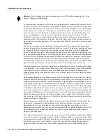
The power supply rests on the floor of the chassis under the card cage and backplane. To remove the
power supply, you must remove the chassis access cover at the noninterface processor end of the
router, remove the power harness cover, and disconnect the harness from the backplane receptacle.
Always pull the harness out by the connector, not by the wires. Before removing the power harness
cover, ensure that the system power is turned off; otherwise, the backplane voltages become a
hazard.
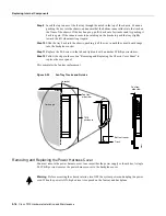
On the AC receptacle on the interface processor end of the 550W power supply, a cable-retention
clip snaps up and around the modular AC power cable connector to prevent the cable from
accidentally being pulled out or from falling out. (See Figure 5-28.) When inserting the power
supply, this clip can get snagged on the chassis floor. Before inserting the supply, remove the clip or
tape it up out of the way.
For the DC-input power cable, for the 600W DC-input power supply, strain relief is provided by a
nylon cable tie that fastens the power cable to the terminal block cover. You provide this cable tie.
Caution
To prevent damage, always pull the connector, not the harness wires, to disconnect the
power harness.
Figure 5-28
AC Power Supply, Interface Processor End
Warning
Before accessing the chassis interior, turn OFF the system power and unplug the power
cable. When the power is ON, high current is exposed on the fan tray and backplane.
Removing the Power Supply
Follow these steps to remove the power supply:
Step 1
Turn OFF the system power switch and disconnect the power cable from the power source.
Step 2
Follow Steps 1 and 2 in the section “Removing and Replacing the Chassis Cover Panel.”
Step 3
Follow Steps 1 through 5 of the section “Removing and Replacing the Power Harness
Cover” to remove the power harness cover.
Step 4
Put on an antistatic strap (your own or the one supplied with the spare fan tray) and connect
the equipment end to any unpainted surface on the chassis body.
Step 5
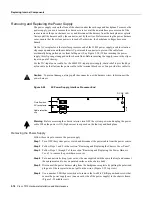
Disconnect the power harness plug from the backplane receptacle by pulling the polarized
plug out of the receptacle; do not pull on the wires. (Figure 5-29 top view.)
Step 6
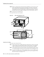
Use a number 2 Phillips screwdriver to remove the two M-4 Phillips pan-head screws that
secure the power supply ears (one on each side of the power supply) to the chassis frame.
(Figure 5-29 middle view.)
AC receptacle
On/off switch
Cable retention
clip
DC OK LED
H1998
Содержание TelePresence Server 7010
Страница 10: ...x Cisco 7010 Hardware Installation and Maintenence ...
Страница 14: ...iv Cisco 7010 Hardware Installation and Maintenance Document Conventions ...
Страница 112: ...2 52 Cisco 7010 Hardware Installation and Maintenance Initial Configuration Information Page ________ ...
Страница 148: ...3 36 Cisco 7010 Hardware Installation and Maintenance Using the Flash Memory Card ...
Страница 158: ...4 10 Cisco 7010 Hardware Installation and Maintenance Troubleshooting the Processor Subsystem ...
Страница 242: ...5 84 Cisco 7010 Hardware Installation and Maintenance Replacing Internal Components ...
Страница 258: ...A 16 Cisco 7010 Hardware Installation and Maintenance MIP Interface Cable Pinouts ...
Страница 270: ...B 12 Cisco 7010 Hardware Installation and Maintenance Interface Processor LEDs ...
Страница 274: ...C 4 Cisco 7000 Hardware Installation and Maintenance ...
Страница 287: ...Index 13 ...


