


Maintenance 5-79
Replacing Internal Components
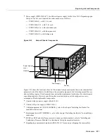
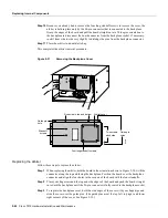
Step 7
Using both hands, grasp both of the power supply handles and pull the power supply about
halfway out of the bay (Figure 5-29 middle view), then grab the sides of the supply and pull
it out of the chassis. (Figure 5-29 lower view.)
This completes the power supply removal procedure.
Figure 5-29
Removing and Replacing the Power Supply
Removing/replacing
power supply
Handling the
power supply
H1995
Phillips screws
(2 places)
Power harness
Backplane
power
receptacle
Power supply ears
Содержание TelePresence Server 7010
Страница 10: ...x Cisco 7010 Hardware Installation and Maintenence ...
Страница 14: ...iv Cisco 7010 Hardware Installation and Maintenance Document Conventions ...
Страница 112: ...2 52 Cisco 7010 Hardware Installation and Maintenance Initial Configuration Information Page ________ ...
Страница 148: ...3 36 Cisco 7010 Hardware Installation and Maintenance Using the Flash Memory Card ...
Страница 158: ...4 10 Cisco 7010 Hardware Installation and Maintenance Troubleshooting the Processor Subsystem ...
Страница 242: ...5 84 Cisco 7010 Hardware Installation and Maintenance Replacing Internal Components ...
Страница 258: ...A 16 Cisco 7010 Hardware Installation and Maintenance MIP Interface Cable Pinouts ...
Страница 270: ...B 12 Cisco 7010 Hardware Installation and Maintenance Interface Processor LEDs ...
Страница 274: ...C 4 Cisco 7000 Hardware Installation and Maintenance ...
Страница 287: ...Index 13 ...