Advantech IPC-610-H Скачать руководство пользователя страница 1


IPC-610-H


4U Rackmount Chassis 

User’s Manual


Содержание IPC-610-H

Страница 1: ...IPC 610 H 4U Rackmount Chassis User s Manual...

Страница 2: ...or any infringements of the rights of third parties which may result from its use Acknowledgments PC LabCard is a trademark of Advantech Co Ltd IBM and PC are trademarks of International Business Mach...

Страница 3: ...ort website at http www advantech com support Note DDDDDDDDDDDDDDDDDDDDDDDDDDDDDDDDDDDDDDDDD DDDDDDDDDDDDDDDDDDDDDDDDDDDDDDDDDDDDDDDDD DDDDDDDDDDDDDDDDDDDDDDDDDDDDDDDDDDDDDDDDD DDDDDDDDDDDDDDDDDDDDDDD...

Страница 4: ...Flow Chart 6 CHAPTER 2 SYSTEM SETUP 8 2 1 SYSTEM INSTALL 8 2 1 1 Attaching the handles 8 2 1 2 Removing the top cover 8 Figure 2 1 8 2 1 3 Chassis Front and Rear Sections 9 Figure 2 2 9 Figure 2 3 10...

Страница 5: ...2 5 INSTALLING CPU CARDS ADD ON CARDS 15 APPENDIX A BACKPLANE 18 Figure 1 1 18 Table 1 1 Connectors 19 Table 1 2 Routing Table 20 v...

Страница 6: ......

Страница 7: ...General Information 1 CHAPTER...

Страница 8: ...itical environment 24 hours a day 7days a week 1 2 Specifications General Construction Heavy duty steel chassis Drive bay Shock proof Front accessed three 5 25 one 3 5 drivers Cooling system Dual easy...

Страница 9: ...1 2 sine wave Acoustic Noise Less than 52 dB sound pressure at 5 to 28 C 41 to 82 F Altitude 0 to 3048m 0 to 10 000 ft Slide rails General Device C 300 series supported Dimensions 482 W x 173 H x 480...

Страница 10: ...3 2 Class D TUV Nordic CB CCC 100 000 hours 25 275W load PS 400ATX Z ATX PFC 400 W AC 90 264V Full range 5V 42A 3 3V 20A 12V 14A 12V 1A 5V 1A 5 Vsb 0 75 A 5V 2 5A 12V 0 5A UL cUL TUV CCC 100 000 hours...

Страница 11: ...A 6114P4 C CCC IPC 610BP 00XH w o w o None IPC 610BP 25ZH PS 250ATX Z ATX PFC w o CCC IPC 610BP 30ZH PS 300ATX Z ATX PFC w o CCC IPC 610MB 00XH w o w o None IPC 610MB 25ZH PS 250ATX Z ATX PFC w o None...

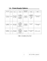
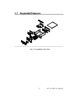
Страница 12: ...1 7 Exploded Diagram Fig 1 2 Installation Flow Chart IPC 610 H User s Manual 6...

Страница 13: ...System Setup 2 CHAPTER...

Страница 14: ...nician 2 1 1 Attaching the handles The handles for the front panel are in the accessory box To install the handles simply secure them to the front panel with the screws provided 2 1 2 Removing the top...

Страница 15: ...ide of door cover there are system LED status and key lock switch The USB and P S 2 keyboard connector are on the left side of front panel Figure 2 2 Power On Off Switch System Reset Figure 2 3 System...

Страница 16: ...onnect with system you could use this connector PS 2 connector If you want to connect PS 2 keyboard you could use this connector The rear section of B P version includes B P rear window The rear 14 sl...

Страница 17: ...n and four screws fixing the Standard Drive Bay on right side 3 Lift off the Standard Drive Bay See Figure 2 4 4 Insert the drives into their proper locations in the drive bay and secure them with the...

Страница 18: ...of Backplane and ATX feature connector CN20 of SBC finally connect POWER SW wire with the ATX soft power switch CN21 on SBC to finish the installation 2 2 2 IPC 610MB 00XH ACP 610MB 00X is for M B us...

Страница 19: ...ignals LED Description Light No light 3 3V 3 3V signal Normal No output 5V 5V signal Normal No output 12V 12V signal Normal No output 5V 5V signal Normal No output 12V 12V signal Normal No output 5Vsb...

Страница 20: ...by blowing air inward Please refer the Figure 2 5 and Figure 2 6 to replace the defective fan Press the location A and then pull the B which is showed on Figure 2 6 then the connector could be release...

Страница 21: ...board computers and other add on boards Remove the chassis cover Take out the hold down cramp Insert the CPU or add on cards on suitable location Align and fix the screw to tighten the card to a fixe...

Страница 22: ......

Страница 23: ...Backplane A APPENDIX...

Страница 24: ...Appendix A Backplane PCA 6114P4 C 1 20 32 5 7 21 3 64 5 5 1 45 72 40 94 71 68 78 74 20 32 16 51 20 32 12 7 2 54 8 25 83 17 26 5 315 Figure 1 1 IPC 610 H User s Manual 18...

Страница 25: ...signal 3 pin connector CN2 8 pin Alarm Board Power connectorr CN3 3 pin 5V and 12V Power connector CN1 PIN Name 1 PS ON 2 GND 3 5VSB CN2 PIN Name 1 5VSB 2 GND 3 GND 4 5V 5 5V 6 3 3V 7 12V 8 12V CN3 P...

Страница 26: ...uting Table PCA Slot IDSEL PCI Interrupt Pin Route INT A INT B INT C INT D PCI1 AD31 INT B INT C INT D INT A PCI2 AD30 INT C INT B INT C INT D PCI3 AD29 INT D INT A INT B INT C PCI4 AD28 INT A INT B I...

Отзывы: