


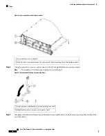


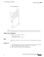

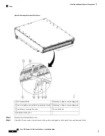


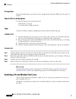


Figure 41: DC Terminal Block Cover
Install the terminal block cover after the input wiring is installed, but before power has been energized.
Caution
Required Tools and Equipment
You need the following tools to perform this task:
• ESD-preventive wrist strap
• 6-in. long Number 1 Phillips screwdriver
Steps
To install the DC terminal block covers, go to the rear (MSC) side of the chassis and perform the following
steps:
SUMMARY STEPS
1.
Attach the ESD-preventive wrist strap to your wrist and connect its leash to one of the ESD connection
sockets on the front (PLIM) side of the chassis or a bare metal surface on the chassis.
2.
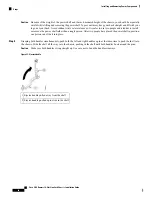
Align the DC terminal block cover with the cover latch tab.
3.
Use the screwdriver to secure the screw into the mounting standoff.
Cisco CRS Routers 16-Slot Line Card Chassis Installation Guide
75
Installing and Removing Power Components
Required Tools and Equipment
Содержание CRS-16-LCC/M
Страница 20: ...Cisco CRS Routers 16 Slot Line Card Chassis Installation Guide xx Preface Preface ...
Страница 118: ...Cisco CRS Routers 16 Slot Line Card Chassis Installation Guide 98 Installing and Removing Power Components Steps ...
Страница 252: ...Cisco CRS Routers 16 Slot Line Card Chassis Installation Guide 232 Upgrading Chassis Components Steps ...


