


When a cable is removed from the rear of the DC modular configuration power shelf, we recommend that it
should be wrapped with standard black electrical tape.
Note
Step 5
Replace the terminal block cover.
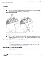
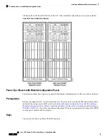
Removing Modular Configuration AC Power Shelf Wiring
This section describes how to remove input AC cords from the rear of the modular configuration DC power
shelf.
Prerequisites
Before performing this task, power down and remove AC PMs and the alarm module in the shelf you want
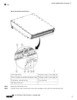
to disconnect.Remove the upper grille from the rear (MSC) side of the chassis, if installed.
Before removing wiring from the power shelf, make sure that the input power cables are not energized.
Note
Required Tools and Equipment
• 6-in. long number 1 Phillips screwdriver
Steps
To remove the input AC cords, go to the rear of the chassis and perform the following steps:
SUMMARY STEPS
1.
Use the screwdriver to loosen the screws that clamp the cords in place.
2.
Remove the cords from the cord clamps.
DETAILED STEPS
Step 1
Use the screwdriver to loosen the screws that clamp the cords in place.
Cisco CRS Routers 16-Slot Line Card Chassis Installation Guide
81
Installing and Removing Power Components
Removing Modular Configuration AC Power Shelf Wiring
Содержание CRS-16-LCC/M
Страница 20: ...Cisco CRS Routers 16 Slot Line Card Chassis Installation Guide xx Preface Preface ...
Страница 118: ...Cisco CRS Routers 16 Slot Line Card Chassis Installation Guide 98 Installing and Removing Power Components Steps ...
Страница 252: ...Cisco CRS Routers 16 Slot Line Card Chassis Installation Guide 232 Upgrading Chassis Components Steps ...


