

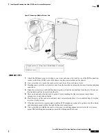


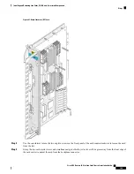


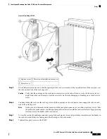

Step 2
Identify the LCC fan controller card to be removed from the card cage. Use the screwdriver to turn the two captive screws
on the front panel of the card counterclockwise to loosen it from the slot.
Step 3
Grasp the two card ejector levers and simultaneously pivot both ejector levers 90 degrees (70 degrees for a new LCC fan
controller card) away from the front edge of the card carrier to unseat the card from the midplane connector.
Step 4
Touching only the metal card carrier, slide the card from the slot and place it directly into an antistatic sack or other
ESD-preventive container. If you plan to return the defective card to the factory, repackage it in its original packaging.
What to do next
After performing this task, close the front (PLIM) side cosmetic doors.
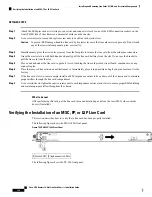
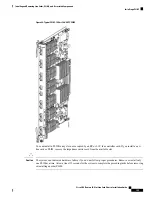
Verifying the Installation of an LCC Fan Controller Card
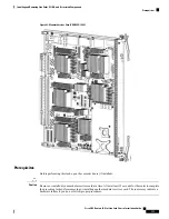
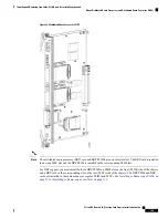
This section describes how to verify that the LCC fan controller card has been properly installed. The following
figure shows the LCC fan controller front panel.
Figure 78: LCC Fan Controller Card Front Panel
Status LED
5
Alphanumeric LEDs
3
External Clock 1 port
1
Alphanumeric LEDs
4
External Clock 2 port
2
Understanding the Alphanumeric LEDs
At one end of the faceplate, near an ejector lever, an LCC fan controller card has two four-digit alphanumeric
LED displays that show a sequence of messages indicating the state of the card.
It is normal for some displayed messages to appear too briefly in the LED display to be read.
Note
Troubleshooting the LCC Fan Controller Card
If the installed or replaced LCC fan controller card fails to operate or to power up on installation:
• Make sure that the card is seated firmly in the LCC slot. One easy way to verify physical installation is
to see whether the front faceplate of the LCC fan controller card is even with the fronts of the other cards
installed in the card cage.
• Check whether the ejector levers are latched and that the captive screws are fastened properly. If you are
uncertain, unlatch the levers, loosen the screws, and attempt to reseat the LCC fan controller card.
• Examine the alarm module to see if there are any active alarm conditions. See
System 16-Slot Line Card Chassis System Description
for information on the alarm module.
Cisco CRS Routers 16-Slot Line Card Chassis Installation Guide
143
Installing and Removing Line Cards, PLIMs, and Associated Components
Verifying the Installation of an LCC Fan Controller Card
Содержание CRS-16-LCC/M
Страница 20: ...Cisco CRS Routers 16 Slot Line Card Chassis Installation Guide xx Preface Preface ...
Страница 118: ...Cisco CRS Routers 16 Slot Line Card Chassis Installation Guide 98 Installing and Removing Power Components Steps ...
Страница 252: ...Cisco CRS Routers 16 Slot Line Card Chassis Installation Guide 232 Upgrading Chassis Components Steps ...


