
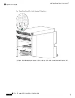


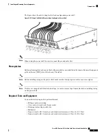


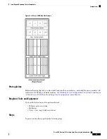


The figure shows the cable wiring for the fixed configuration power shelf.
Figure 22: DC Power Shelf Cable Wiring for Fixed Configuration Power Shelf
When wiring the power shelf, be sure to connect the ground cable first.
Note
Prerequisites
Before performing this task, ensure that both power shelves are installed in the chassis. Remove the upper air
grille on the rear [MSC] side of the chassis, if installed.
Before installing wiring on the power shelf, make sure that the input power cables are not energized.
Note
If cables are wrapped with black electrical tape, be sure to remove tape from cables before installing wiring
on the power shelf.
Note
Required Tools and Equipment
You need the following tools to perform this task:
• ESD-preventive wrist strap
• 3/8 in. ratchet wrench with 10-mm socket
• Crimping tool and lug specific die
• Multimeter
• Torque wrench with 10-mm 6 pt. socket and rated accuracy at 30 in.-lb (3.39 N-m)
• Torque wrench with 10-mm 6 pt. socket and rated accuracy at 20 in.-lb (2.26 N-m)
Cisco CRS Routers 16-Slot Line Card Chassis Installation Guide
39
Installing and Removing Power Components
Prerequisites
Содержание CRS-16-LCC/M
Страница 20: ...Cisco CRS Routers 16 Slot Line Card Chassis Installation Guide xx Preface Preface ...
Страница 118: ...Cisco CRS Routers 16 Slot Line Card Chassis Installation Guide 98 Installing and Removing Power Components Steps ...
Страница 252: ...Cisco CRS Routers 16 Slot Line Card Chassis Installation Guide 232 Upgrading Chassis Components Steps ...


